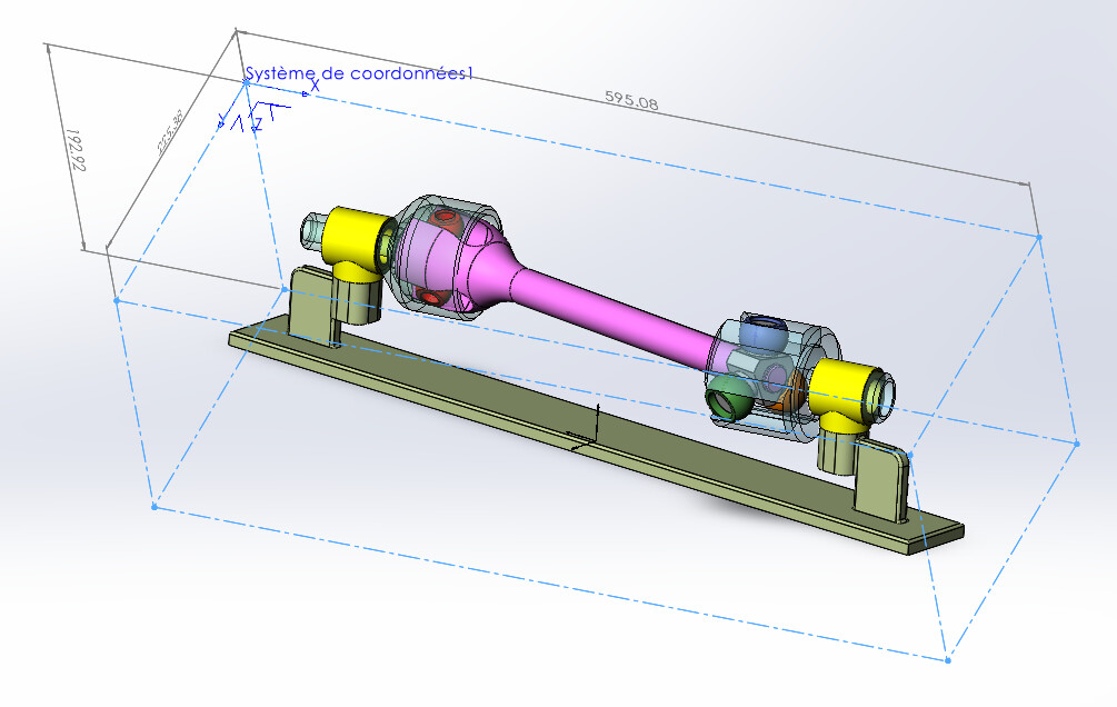
Visualization Cube

Thank you very much for these answers.

So the error varies according to the assemblies and parts.
This ranges from 0.5 to 1.5mm.
In my case this is not necessarily important, because I get my values back to the cm.

My question was mainly in order to better understand the code and possibly correct it if it was feasible. So nothing imperative.

I still put the assembly + parts with 3D Sketch + System coordinates generated by the macro if you want to look.

Thanks for the information :slight_smile:

TEST ENCOMBREMENT.rar (1.1 MB)

1 Like

Great job @m.blt , as always.
And I thought I'd never have to use the " BoundingBox " until now... I come across a client, let's say... Fussy.
Your Macro is therefore timely. Thank you :index_pointing_at_the_viewer: :+1: :+1: :index_pointing_at_the_viewer:

2 Likes

Hello @Maclane , and thank you for the compliment...
However, beware of the problem of precision raised by @MLG in his last message.
I noticed the anomaly, but I couldn't identify if it's SW or the macro that is at fault.

3 Likes

Hello;
This is a recurring problem with splines, Solidworks only takes into account the points and not the curve itself so I think the " GetExtremePoint() " function does the same thing (as its name suggests).

For my part, I took the liberty of modifying your macro by adding the properties to the document with an option to register them (or not) in all configurations.
On the other hand, I'm looking for how to add dimensioning on the 3D sketch.

I haven't looked at the notion associated with the " Delete " button yet, but I think that by renaming the " 3Dsketch " and " Coordinate System" functions in a more explicit way (like " BoundingBox_3D " and " BoundingBox_XYZ "), it will be easier to delete them, or even to delete all the functions (leftovers) with the same Names (+counter).

Kind regards.

3 Likes

Hello @MLG

Maybe the values will be more accurate with all the quality settings maxed out, in the document options?

1 Like

Hi all
The difference is really minimal but is indeed present.
Having documents listed by hand and some using this macro, we ended up with different output data, hence my question...
And for splines, we avoid working with them so as not to have this kind of problem.

Hi everyone
HOP, here I am back on this subject! :slight_smile:
The macro works well, but I find myself facing a problem.
Explanations:

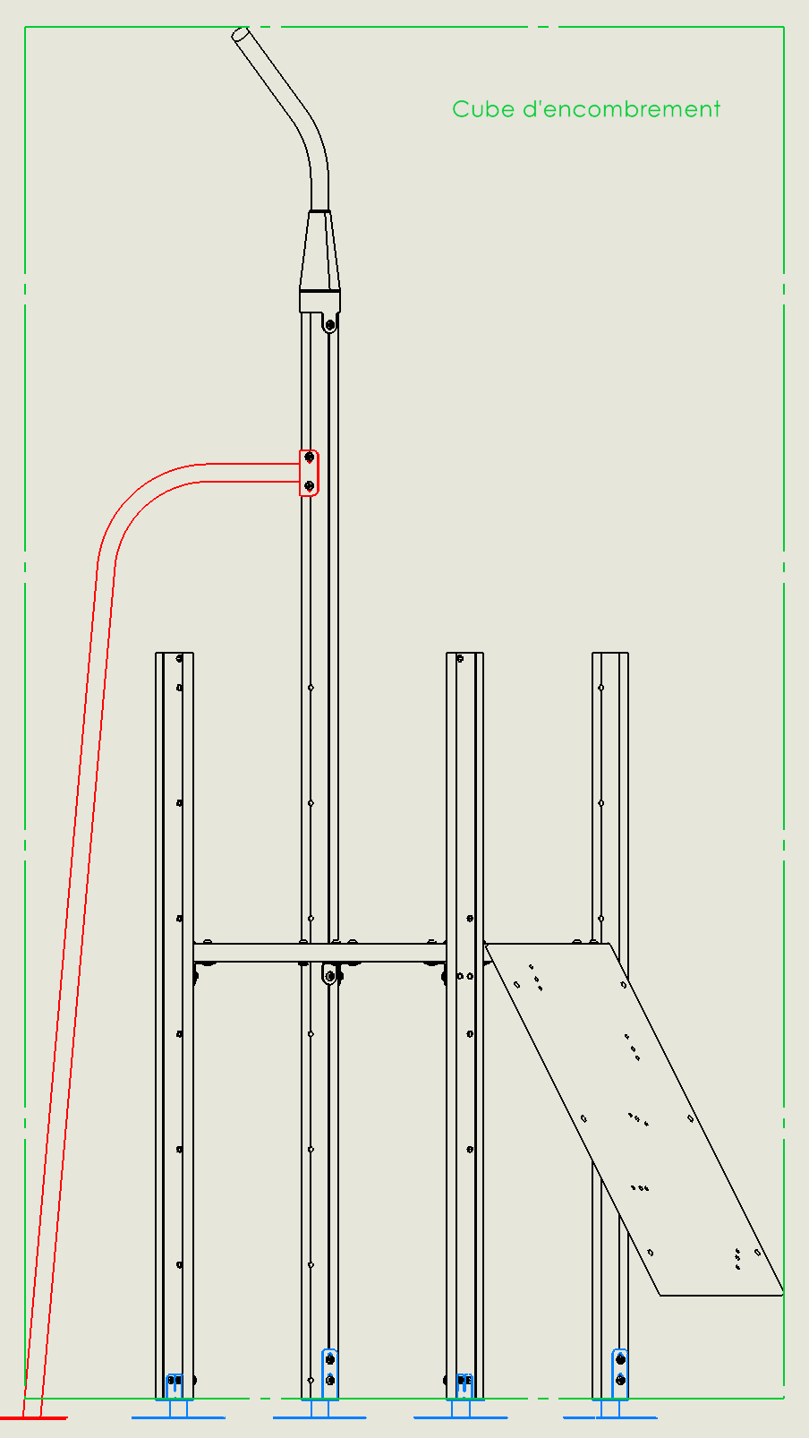
The macro was used to define a 3D cube allowing me to retrieve the footprint values of my assembly according to a precise orientation. For this nickel and a BIG THANK YOU to @m_blt and to all those who participated in the advancement of this post :+1:.

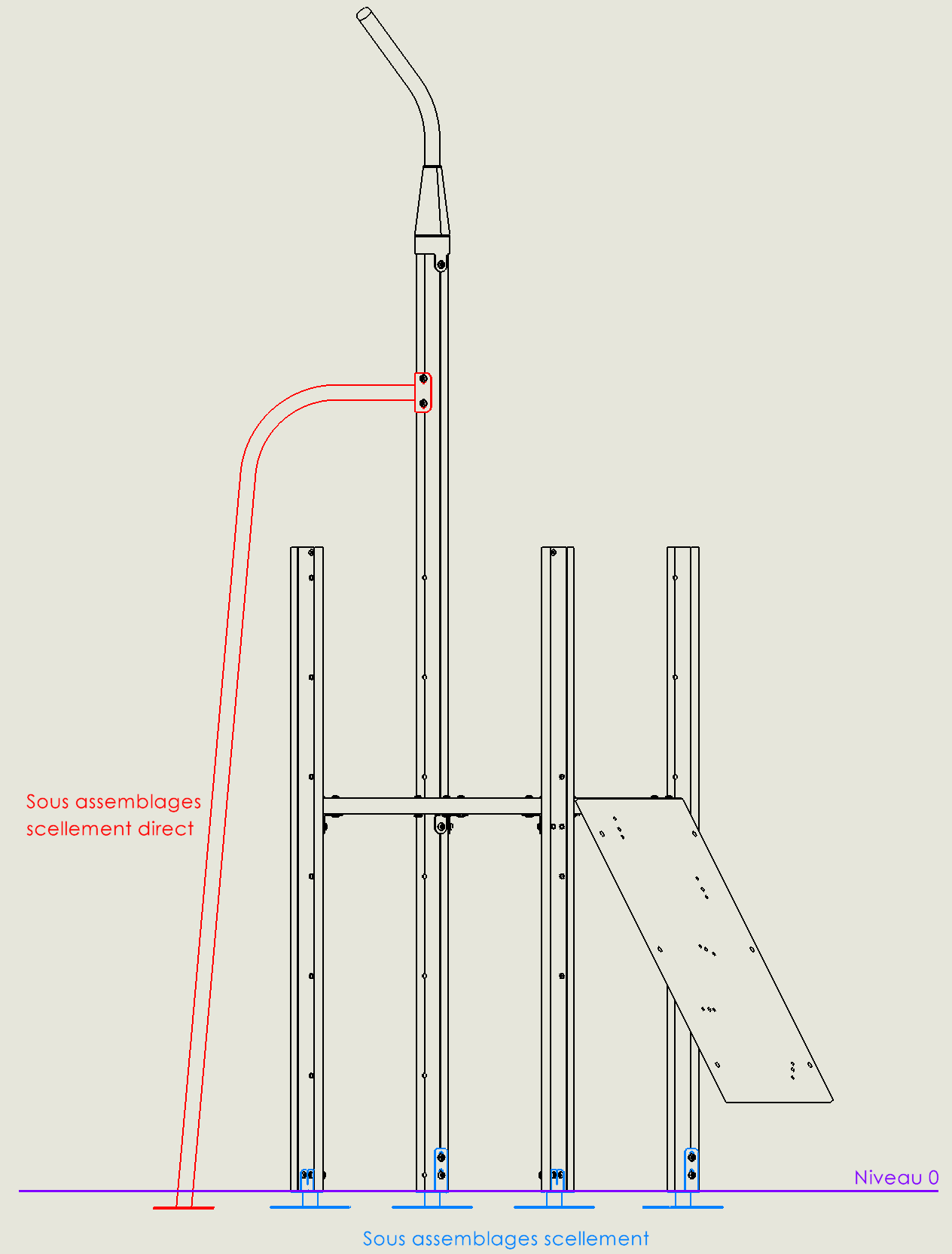
My assemblies have sealing sub-assemblies (below in blue) to fix the product to the floor. In my macro, I deleted these sub-assemblies so that I only had the part above the ground of present. However, I have sub-assemblies in direct sealing (below in red), i.e. they are present below and above level 0 (below without being able to be split/separated:

image

I would like to know if it is possible to add to the UserForm the selection of the level 0 plane (a plane or a part face) in order to determine the lowest plane of the 3D cube? Sub-assemblies in direct sealing (in red) cannot be deleted because they are used to define the width of the cube:

image

The selection of the Level 0 plan would therefore have to define the LOW plane of the cube and the length/width/height footprint would have to be defined only with everything above Level 0 without taking into account what is below.

I hope it's understandable because it's not easy to explain :sweat_smile:

Hello MLG,

A year later, back to the cube... :wink:
image

The principle of macro processing is based on traversing the assembly tree to find the components that limit the dimensions of the cube. Taking into account a plan that cuts certain components to exclude some of them seems complicated at first glance.

Unless...
A clue: It should be possible if this " Level 0 " plane is the reference plane of the creation of the cube (first plane selected in the macro), or at worst parallel to one face of the future cube.
You must select this " limiting " plane (Level 0) in addition to the two entities used to orient the faces of the cube, and not consider what is underneath (which side is below?).
Acceptable?

4 Likes

Back home, sorry, I started the topic and escaped on something else like a rude guy!!

@m_blt , we had in selection a side of the onnant an orientation of the cube and an edge giving the verticality.
Is it possible to have in addition in the first selection a plane that would be level 0 and thus everything that would be under this plane would not be taken into account in the definition of the cube?

1 Like

Hello;

I'm reviving the subject, and in particular @m_blt , because no matter how hard I try, my attempts end in failure...
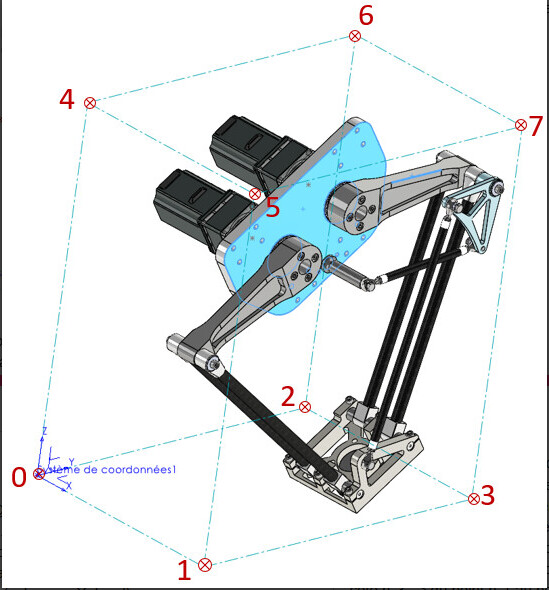
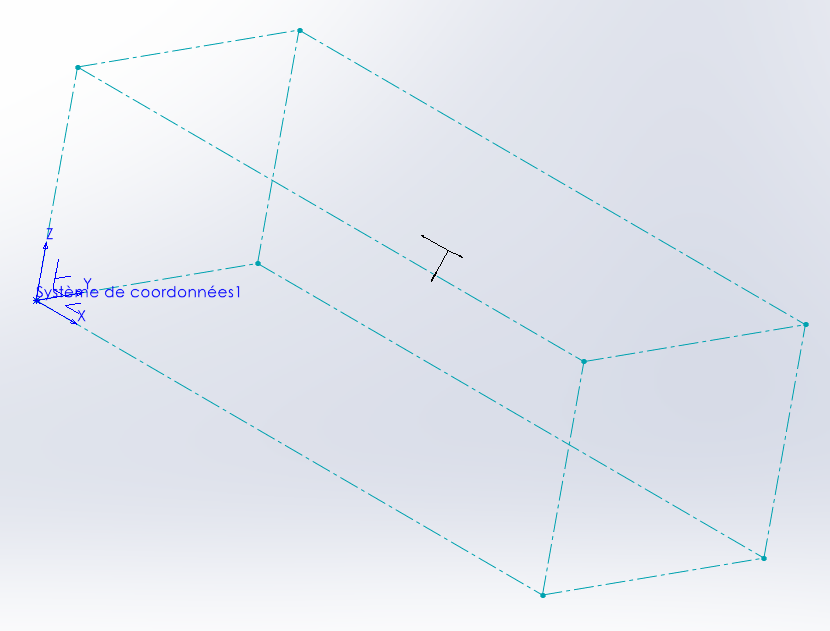
I was looking for a way to add some quotation on the bounding box generated by the macro above... (on the local marker)

dimension n°1 => from point n°0 to point n°1 (according to axis X_local)
dimension n°3 => from point n°0 to point n°2 (according to axis Y_local)
dimension n°2 => from point n°0 to point n°4 (according to axis Z_local)

image

Any ideas to submit to me on how to proceed?

1 Like

I only found this old information, I didn't think it was possible in order to pilot it. If not, it's possible in 3d dressing, I think in 2D, that's for sure. Finally on the 2018 version see links
Dimensioning a Visualization Cube - 2D Plan / Drawing - myCAD Forum (visiativ.com)

I've already figured out how to add the dimensioning on the 2D, but what I would have liked would be the dimensioning driven directly in the 3D sketch.
The goal is for my engineers to be able to see the dimensions of the " Bounding box " directly under Edrawing or to take screenshots directly in the 3D...
They (my engineers) are not always very good with their mouse, and even less with the rating under Edrawing, so you might as well chew the work for them. :yum:

1 Like

I had understood for the quotation the objective being to master your cube.
Originally the purpose of this cube was to define flows, so it adapts to the existing if you want to control the dimensions you will have to create one yourself. And more complicated depending on the orientation but not impossible

engineers on Edraw!! It's already a luxury :stuck_out_tongue_winking_eye: :grin:

2 Likes

Well, no, it's quite the opposite, I don't need driving dimensions, I'm just looking for a way to make the 3 Dimensions appear, visually, in the form of dimensions (piloted) in the 3D sketch of the Cube (and oriented on its new orthonormal coordinate system).
It's still crazy that I can't adapt the code of @m_blt ... yet it provides 98% of the necessary information... :crazy_face:

okOK
In the link I put in you, the person arrived next to you (manually!) but from time to time he didn't manage to do it for no reason.

Bah!
To dimension manually, you might as well do it without going through the macro, after all it is only three dimensions to be added to a cube.
Naively I thought I could easily add them directly into the macro code, but either I'm doing it very wrong (it's quite possible), or adding dimensioning in a 3D sketch via the APIs is not that simple.
However, the @m_blt code gives all the necessary information (or more).
=> I have the Point Name
=> I have the Sketch Name
=> I have the name of the marker
and I even have distances from the 3 X, Yet Z coordinates...
And with all this... well I'm getting there for ... :melting_face: :crazy_face:

Hello @Maclane ,

Sorry for this late reply...
It is not easy to dimension a 3D sketch in a macro.
The headache is to precisely define the position of the odds. We usually just let SW do it, and then we touch it up " by hand ".

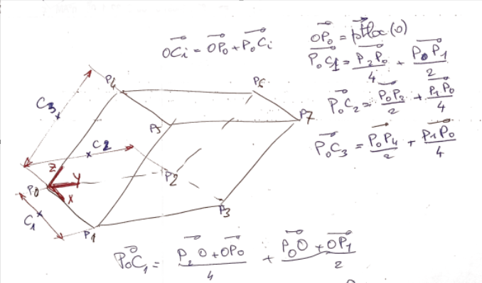
In the " visualization cube" macro, the Sub TraceBox(ptLoc() As MathVector) function draws the box. I added a few lines to it:

  • to best place the three sides of the length of the edges of the box from the origin point P0.
  • to apply a " Fixed " constraint to the eight vertices of the box, so as to freeze the sketch.
  • to create reference points to the vertices of the box, useful in debug mode to identify these vertices. Part of the code to comment out in standard mode.

The result:

In principle :rofl: , it is sufficient to replace the original TraceBox function with the one below.

Sub TraceBox(ptLoc() As MathVector)

        Dim swFeat          As Feature
        Dim swRefPt         As RefPoint
        Dim swFeatMgr       As FeatureManager
        Dim matProps(8)     As Double
        Dim skSegment(11)   As SketchSegment
        Dim swSketch        As Sketch
        Dim posCote(2)      As Double
        Dim noPt            As Long
        Dim boolStatus      As Boolean
        Dim vRefPoint       As Variant
        Dim bInputDimPref   As Boolean
        Dim swDisplayDim    As DisplayDimension
        Dim i               As Long

    swModel.SketchManager.Insert3DSketch True
    swModel.SketchManager.AddToDB = True
    
    Set skSegment(0) = traceLigne(ptLoc, 0, 1)
    Set skSegment(1) = traceLigne(ptLoc, 0, 2)
    Set skSegment(2) = traceLigne(ptLoc, 2, 3)
    Set skSegment(3) = traceLigne(ptLoc, 1, 3)
    
    Set skSegment(4) = traceLigne(ptLoc, 4, 5)
    Set skSegment(5) = traceLigne(ptLoc, 4, 6)
    Set skSegment(6) = traceLigne(ptLoc, 6, 7)
    Set skSegment(7) = traceLigne(ptLoc, 5, 7)
    
    Set skSegment(8) = traceLigne(ptLoc, 0, 4)
    Set skSegment(9) = traceLigne(ptLoc, 1, 5)
    Set skSegment(10) = traceLigne(ptLoc, 3, 7)
    Set skSegment(11) = traceLigne(ptLoc, 2, 6)
    
    ' Contrainte "Fixe" des sommets de la boite
    For noPt = LBound(ptLoc) To UBound(ptLoc)
        boolStatus = swModel.Extension.SelectByID2("", "SKETCHPOINT", ptLoc(noPt).ArrayData(0), ptLoc(noPt).ArrayData(1), ptLoc(noPt).ArrayData(2), False, 0, Nothing, 0)
        If boolStatus Then
            swModel.SketchAddConstraints "sgFIXED"      ' Sommet fixé
        End If
    Next noPt
    
    ' Cotation des arêtes de la boite
    bInputDimPref = swApp.GetUserPreferenceToggle(swUserPreferenceToggle_e.swInputDimValOnCreate)
    swApp.SetUserPreferenceToggle swUserPreferenceToggle_e.swInputDimValOnCreate, False
    
    ' Cote de l'arête / X
    swModel.ClearSelection2 True
    For i = 0 To 2
        posCote(i) = ptLoc(0).ArrayData(i) * 3 / 4 + ptLoc(1).ArrayData(i) / 2 - ptLoc(4).ArrayData(i) / 4
    Next i
'    swModel.SketchManager.CreatePoint posCote(0), posCote(1), posCote(2)
    skSegment(8).Select4 False, Nothing
    skSegment(9).Select4 True, Nothing
    Set swDisplayDim = swModel.AddDimension2(posCote(0), posCote(1), posCote(2))

    ' Cote de l'arête / Y
    swModel.ClearSelection2 True
    For i = 0 To 2
        posCote(i) = ptLoc(0).ArrayData(i) * 3 / 4 + ptLoc(2).ArrayData(i) / 2 - ptLoc(4).ArrayData(i) / 4
    Next i
'    swModel.SketchManager.CreatePoint posCote(0), posCote(1), posCote(2)
    skSegment(8).Select4 False, Nothing
    skSegment(11).Select4 True, Nothing
    Set swDisplayDim = swModel.AddDimension2(posCote(0), posCote(1), posCote(2))

    ' Cote de l'arête / Z
    swModel.ClearSelection2 True
    For i = 0 To 2
        posCote(i) = ptLoc(0).ArrayData(i) * 3 / 4 + ptLoc(4).ArrayData(i) / 2 - ptLoc(1).ArrayData(i) / 4
    Next i
'    swModel.SketchManager.CreatePoint posCote(0), posCote(1), posCote(2)
    skSegment(0).Select4 False, Nothing
    skSegment(4).Select4 True, Nothing
    Set swDisplayDim = swModel.AddDimension2(posCote(0), posCote(1), posCote(2))

    swApp.SetUserPreferenceToggle swUserPreferenceToggle_e.swInputDimValOnCreate, bInputDimPref
    swModel.ClearSelection2 True
    
    ' Réactualiser l'affichage
    swModel.ClearSelection2 True
    swModel.GraphicsRedraw2
    
    Set swSketch = swModel.SketchManager.ActiveSketch
    swModel.SketchManager.AddToDB = False
    swModel.SketchManager.Insert3DSketch True
    
    
'''    ' Création de points de référence aux sommets de la boite
'''    Set swFeatMgr = swModel.FeatureManager
'''    For noPt = LBound(ptLoc) To UBound(ptLoc)
'''        boolStatus = swModel.Extension.SelectByID2("", "EXTSKETCHPOINT", ptLoc(noPt).ArrayData(0), ptLoc(noPt).ArrayData(1), ptLoc(noPt).ArrayData(2), False, 0, Nothing, 0)
'''        If boolStatus Then
'''            vRefPoint = swFeatMgr.InsertReferencePoint(swRefPointSketchPoint, 0, 0.01, 1)       ' Création d'un point de référence
'''            Set swFeat = vRefPoint(0)
'''            swFeat.Name = "Pt" & CStr(noPt)
'''        End If
'''    Next noPt
    
    
    Set swFeat = swModel.FeatureByPositionReverse(0)
    matProps(0) = 0#: matProps(1) = 162# / 255#: matProps(2) = 175# / 255#     'Couleur turquoise
    matProps(3) = 1: matProps(4) = 1: matProps(5) = 0.5
    matProps(6) = 0.4: matProps(7) = 0: matProps(8) = 0
    swFeat.SetMaterialPropertyValues2 matProps, swThisConfiguration, Empty
    UserForm1.Show
    swModel.ForceRebuild3 True
    swModel.ClearSelection2 (True)
        
    swModel.Extension.SelectByID2 "", "EXTSKETCHPOINT", ptLoc(0).ArrayData(0), ptLoc(0).ArrayData(1), ptLoc(0).ArrayData(2), False, 1, Nothing, 0
    swModel.Extension.SelectByID2 skSegment(0).GetName & "@" & swSketch.Name, "EXTSKETCHSEGMENT", 0#, 0#, 0#, True, 2, Nothing, 0
    swModel.Extension.SelectByID2 skSegment(1).GetName & "@" & swSketch.Name, "EXTSKETCHSEGMENT", 0#, 0#, 0#, True, 4, Nothing, 0
    swModel.FeatureManager.InsertCoordinateSystem False, False, False

End Sub

1 Like

Arrrgggghhhhh!

=> set the points... !! FIXING THE !! POINTS
… pfff, but damn, I knew I was on the right track. :sob:

well I had also forgotten the:

swApp.SetUserPreferenceToggle swUserPreferenceToggle_e.swInputDimValOnCreate, False

So it didn't work as well as well. :crazy_face:
Thank you @m_blt and hats off.
(not so simple macro quotation, eh? :sweat_smile:)

1 Like

Above all, you need to have a sheet of paper and a pen near the keyboard to enrich the representations of SW... :disguised_face: :nerd_face: :sunglasses:

image

It's still more complete and more aesthetic than that:

image

3 Likes