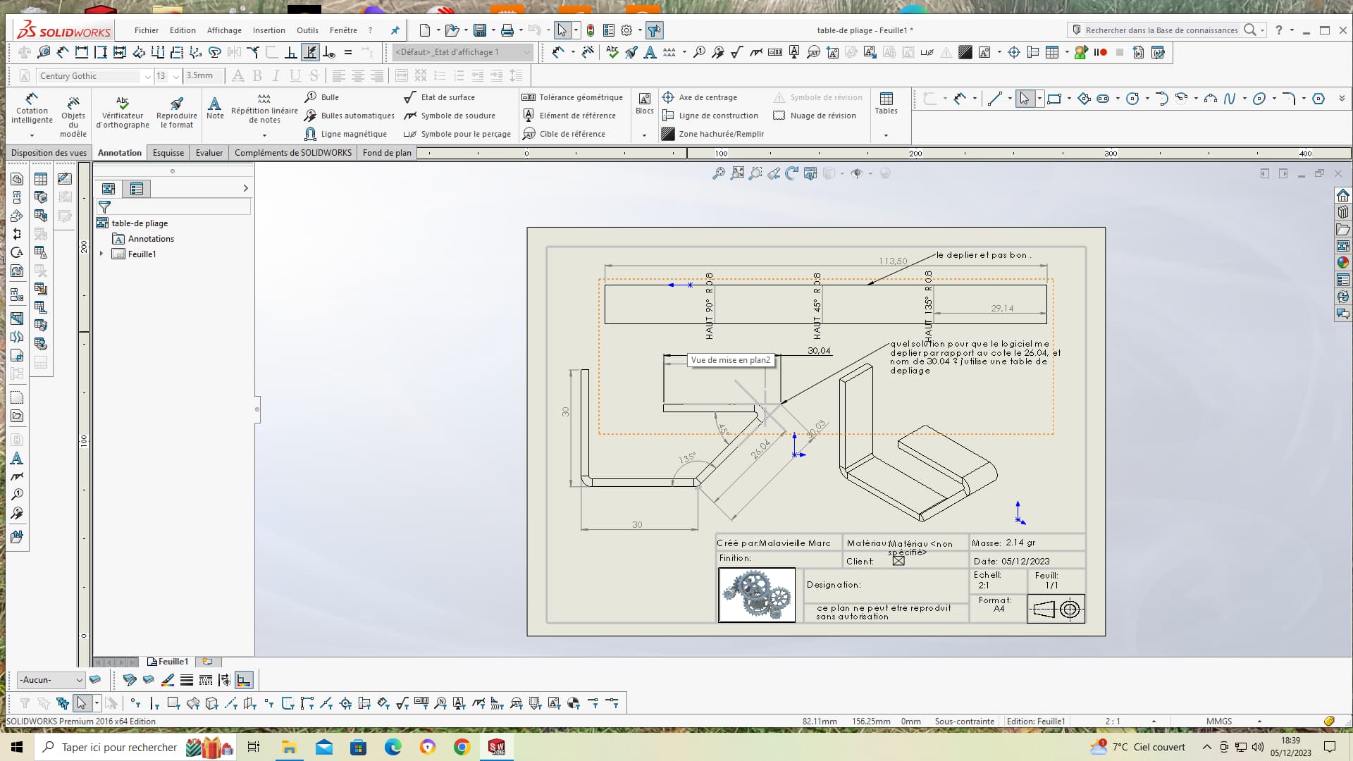
Good evening everyone, do you have a solution, so that on a piece with several folds so 1 with a fold close the dimension taken for the calculation faces on the tangent and name not on the tip? I'm putting a screenshot for more understanding thank you for your answers
Marco.
Hello
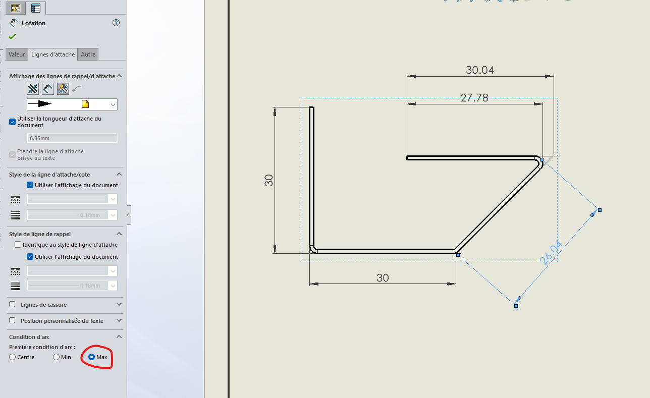
Not sure if I understood the problem but for the display of the rating of 26.04 just have to set the attachment line by having selected the radius.
In the drawing state, there are the points of intersection between the planar faces that are modeled hence the attachment to an entity further away from the radius of the part.
For the unfolded one you would have to see how the 3D model is made, there may be a function that distorts the result.
After I don't know if you have already made this type of part but I have a little doubt about its feasibility (or then you have a specific tool because the end of the bending radius that remains has a very low possibility of coming out)
1 Like
Hello
As Cyril.f points out, I don't understand the meaning of the question!
Hello;
Compared to your screenshot, it seems to me that your part is not 2mm thick...
(thickness rating is missing)
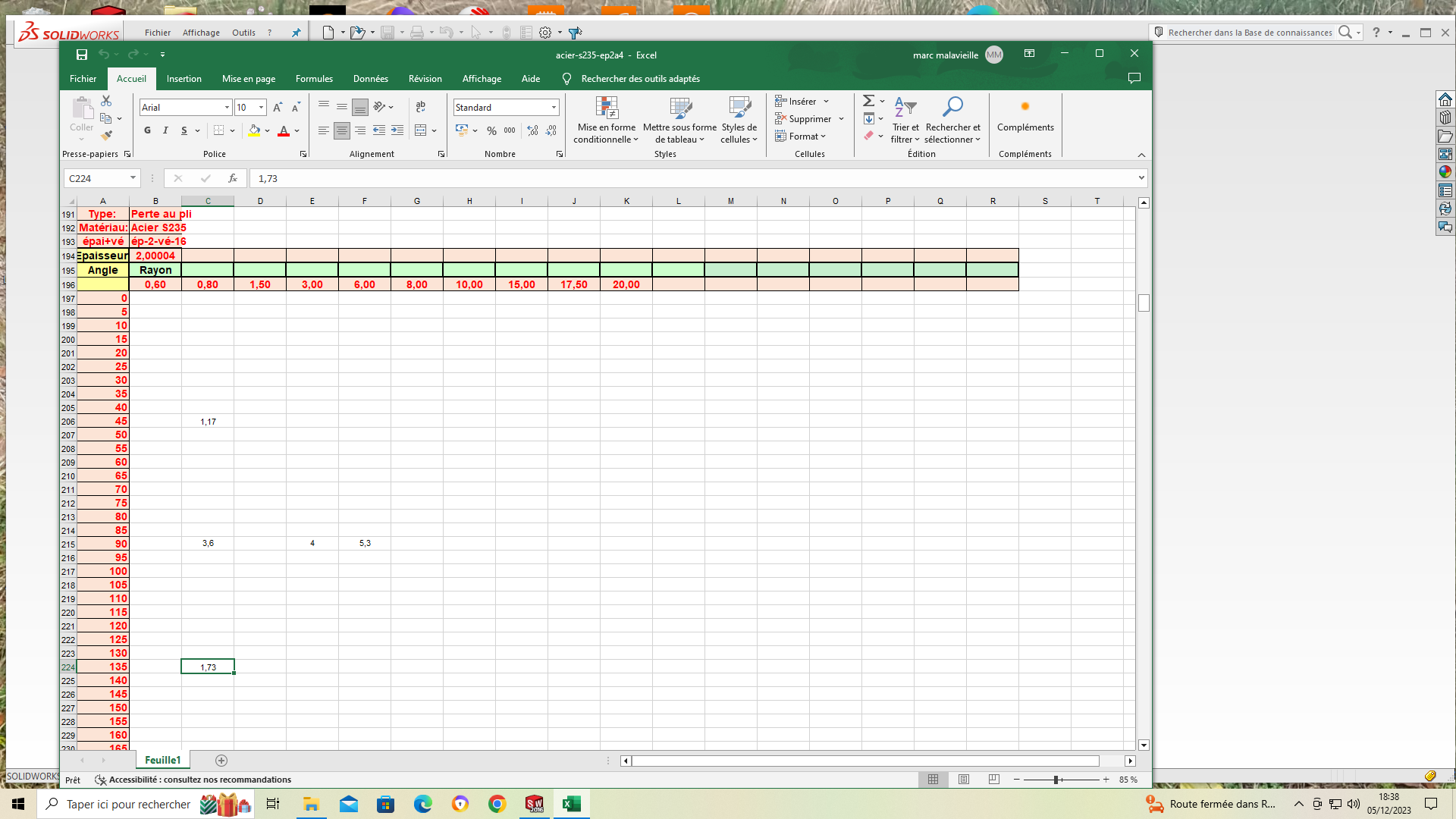
On your second catch, the folding table is for a thickness of 2.00004 mm (!?)
Are your ply sketches inside or outside your sheet metal?
… Not very clear all this.
Can you publish your part (specifying the Solidworks version)?
Kind regards.
1 Like
Hello
As TLM I don't understand the PB well, I agree with Maclane "Not very clear all this". That said, SW is not a sheet metal bomb but make 3 folds...! Nevertheless!
As far as sheet metal parts with a succession of plies are concerned, it is always important to fill in the bending order.
ABES
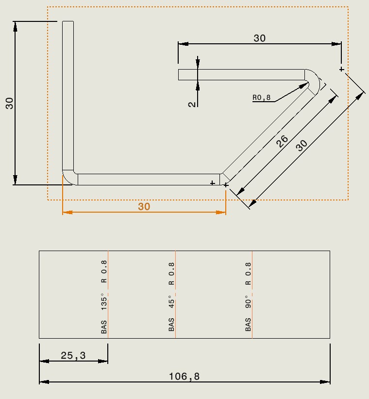
Good evening, I must have a hard time making myself understood, excuse me, I'll put you the 3D parts and the developed,
My question, is there a way for the software to unfold me in relation to the tangent and name not by the tip of the angle at 45° if I add all my outside sides 30+30+26.04+26.04 minus my losses at the bends in the table provided as an example the table gives it 105.88 and name not 113.5 because the software starts at the tip of the angle as shown in the bet in plan and for the table of the thickness 2 but save in excel 200004 because I fold thickness 2 with several widths of ve 12, 25, 16 thank you for your answers
Marco
folding table. SLDPRT (346.8 KB)
folding-tableunfolding. SLDPRT (290.6 KB)
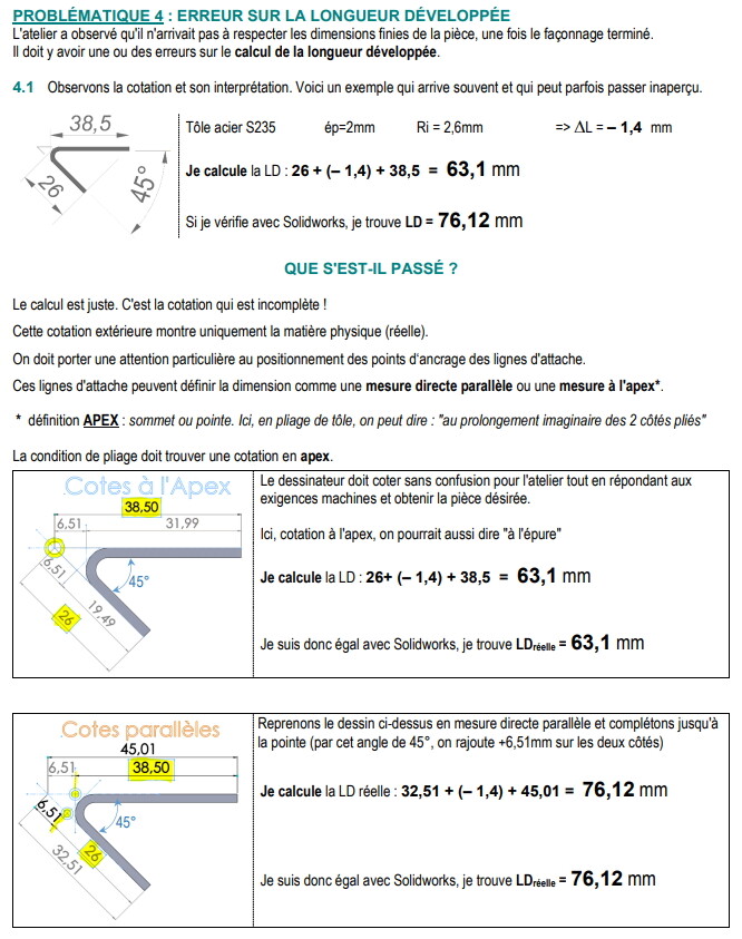
Indeed, when I made the folding tables several years ago, I also encountered this problem.
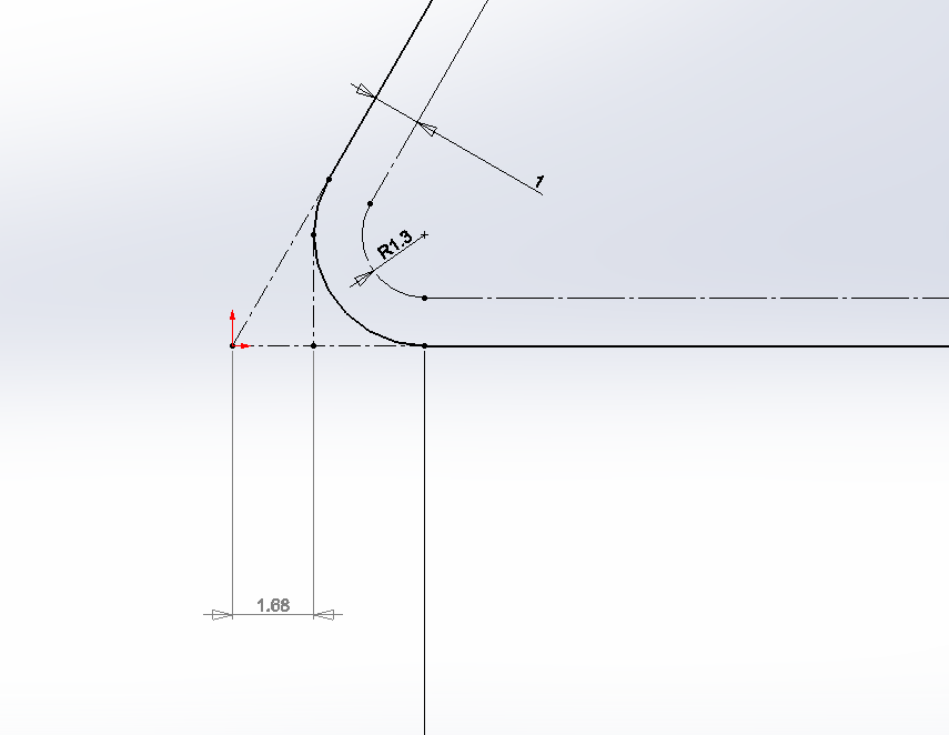
To counter the problem (the Amada folding software in ext starts from the tangency, while SW on the closed angles starts from the point of intersection ext, I had measured the difference on a sketch between the 2 to add it to the loss at the bend in the excel table, in order to have the correct dev value.
For our part, there are few closed-angle tools so it was done quite quickly.
Example here with 1mm sheet metal you have to add 2 times 1.68 to the value of loss at the bend:
2 Likes
Hello
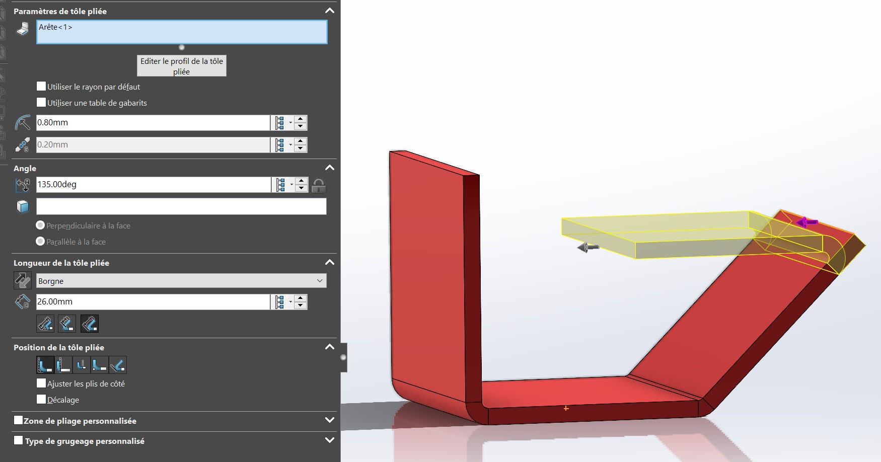
that's what SW gives me with the folding parameters with the tangency option for the 45° fold.
See screenshots.
No problems encountered. On the other hand, I don't have time to test on our press brake if the press brake is correct (it seems to me that we have punches for closed folds).
But in any case SW knows how to dimension a fold / tangent of the curve of the fold.
1 Like
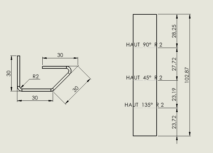
Here is a piece that I made with the parameters of our sheet metal, according to their table included
ep 2 ray 2
Item1.SLDDRW (58.2 KB)
Item1.SLDPRT (146.6 KB)
1 Like
I find 103.1 with 1 K factor of 0.28 which is about 2/10 higher than your result. In sheet metal work, it's correct as a rough tolerance