Hello @ all
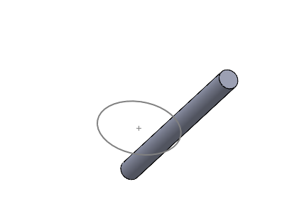
I am trying to constrain a threaded rod so that it rotates on its axis but also in a way that is off-axis with respect to its base, so that it describes a kind of inverted cone.
How would you do that?
Thank you
Hello @ all
I am trying to constrain a threaded rod so that it rotates on its axis but also in a way that is off-axis with respect to its base, so that it describes a kind of inverted cone.
How would you do that?
Thank you
It smells like trigo around here.
Personally, the trick that jumps out at me is to draw a circle on a plane in your assembly and to associate a tangency to your " cylinder "

then it's up to you to determine the height, diameter, etc.
Hello
Proposal without having thought too much, I would say to put a constraint between the axis of the screw and a point at the base of the worm screw and then to constrain in the upper part in tangency of the external geometry of the screw with the sketch of the circle.
Maybe just a problem in the management of the SW tangency which may reverse it from time to time but it seems to me the simplest.
Hello @Cyril.f re @romain_becdelievre Thank you for your answers.
A tangency on geometry, hmm... Given the geometry of a screw, rotating on itself, whose tangency is changing, wouldn't this pose problems? Especially if you are looking for a regular movement.
Possible.
In this case, see to constrain the axis of the screw or a fixed point on the end of the worm screw with the sketch of the circle.
To keep the rotation you have to stay on points or axis.
On the other hand, if I add a cylinder to which I apply all the constraints, then stick the screw on it, it should turn well. But is it really the cleanest and lightest way?
Not necessarily the lightest since it adds a model + additional constraints.
For a hack of this type, you might as well add a cylindrical surface in the worm model and constrain this surface rather than the volume body of the auger.
@Sylk
Sketching a point at the bottom of the rod + cylinder in the form of a surface is certainly the "lightest " way.
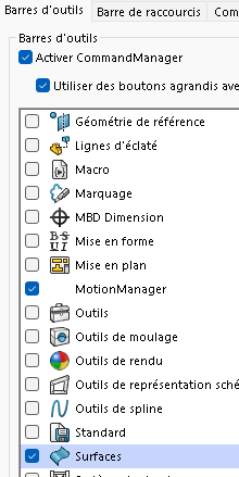
At home the surface toolbar is disabled by default, it's a small box to check if needed.

Otherwise another trick, trajectory constraint with a point on the top of the worm screw and the circle of the sketch.
A constraint between the axis of the screw and the point of origin of the rotation and normally it does the job.
Well precisely @Cyril.f the trajectory was my first intention, but I hadn't succeeded because the tops of the screw were incompatible or I don't know what problem, and I didn't have an axis on my old screw modeled with a helix, but there I redid it, I created a thread profile to use it with the function, and therefore with a " supplied " axis. It should be more flexible already.
On a cylindrical geometry, unless I'm mistaken, there is always a present axis. Just display the temporary axis (same to create the point at the intersection between this axis and the surface of the screw)
Uh, no, I'm saying something stupid, since here the " conical " rotation is linked to the rotation of the virtual engine, the inner and outer tangents are always the same so a priori it's still a viable solution. Sorry for the mistake.
With a distance constraint it should work:
Sketch the axis of the cone seen in the image.
Constrain the bottom end point of the screw with the end point of the shaft with a coincidence.
Constrain the top end point of the screw with a distance from the axis.
I can't get anywhere. And even tilted when it turns it's on the spot... not fucked up to ride alone on a line...