
Hello, I would like to be assisted in designing in 3d my exhaust on solidworks student 2025 that I made in paper in order to refine the angles and sides, thank you very much for your feedback.
Hello Burt_Munoro,
For my prt, I would go through a 3D sketch with a spline, with the different sections desired.
For the moment I can't take screenshots, but as soon as I have my hand on my PC, I will.
…@+.
Good luck.
AR+.
Hello,
For my part, I will opt to actually start with a 3D spline and then make a succession of planes + sketches on each plane in order to be able to use the " Bossing/Smoothed Base" function with a different diameter on each plane
1 Like
What is the final goal, to get a plan out of each sheet with the press or just to have a realistic 3d plan.
The starting bases will not be the same depending on the need.
1 Like
I think it's a good exercise on SW and indeed if it's for shape optimization it will be an interesting step added to a 3D print.
Otherwise for the developed, since the mufflers are generally made with very thin sheet metal, the unfolded paper should be enough.
1 Like
Hello
3D sketch, but I'll start with different straight lines to define the trajectory (relying on a spline why not). Using lines and endpoints I created plans and sketches defining the sections. And by thin sweeping I create the surfaces.
1 Like
Hello @Burt_Munro ,
Is it for a scale model, a motorcycle (probably given the nickname... ![]() )?
)?
What scale, what dimensions? How is it made?
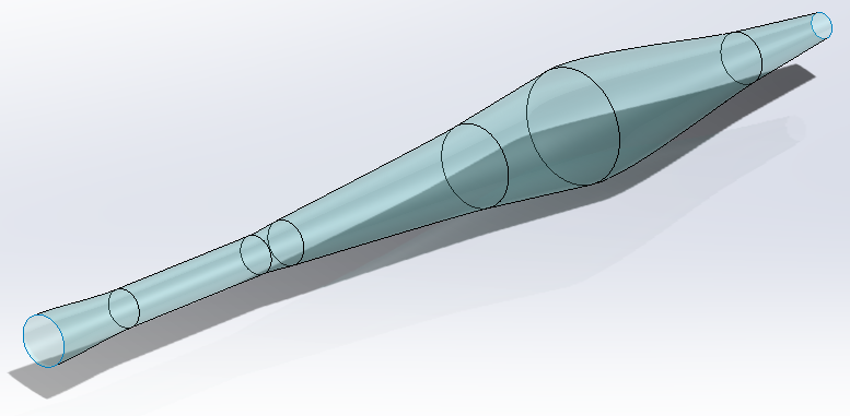
One possible way is to generate the surface of the pot in a "straight" version (see image below), and use the Solidworks Bending function to make the 5 bends...
The main problem will be to manage the angles.
1 Like
In the end, less trouble than expected.
Even if the bending seen by Solidworks is not crystal clear.
It's a pity that the sketches don't follow the body in its deformation.
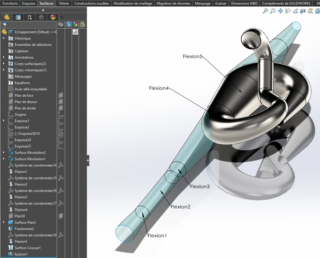
Result attached (SW 2022).
Escape.SLDPRT (2.2 MB)
4 Likes
@m_blt
It's not bad this piece ![]()
On the other hand, the level of precision of the Bending function is a little limited in memory ![]()
Hello @FRED78 ,
In fact, the bending function is precise, but it transforms the geometric nature of the entities. For example, the circular straight sections of the initial shape (surface of revolution) become generic splines after " bending ". It is probably the only type of entity that allows the part to be deformed while maintaining its general appearance.
However, the difference observed between an initial circular section of 60 mm in diameter and its conversion to a spline after bending is only 0.003 mm (3 microns).
For an exhaust pipe, it seems acceptable to me. ![]()
Yes for an exhaust pipe it's acceptable.
On the other hand for the developed ones ![]() .
.
We would have to make cuts like in the initial photo to see if we can make developed ones with the sheet metal tool for each conical section
Good evening,
The answer is yes, we can. The proof in pictures:
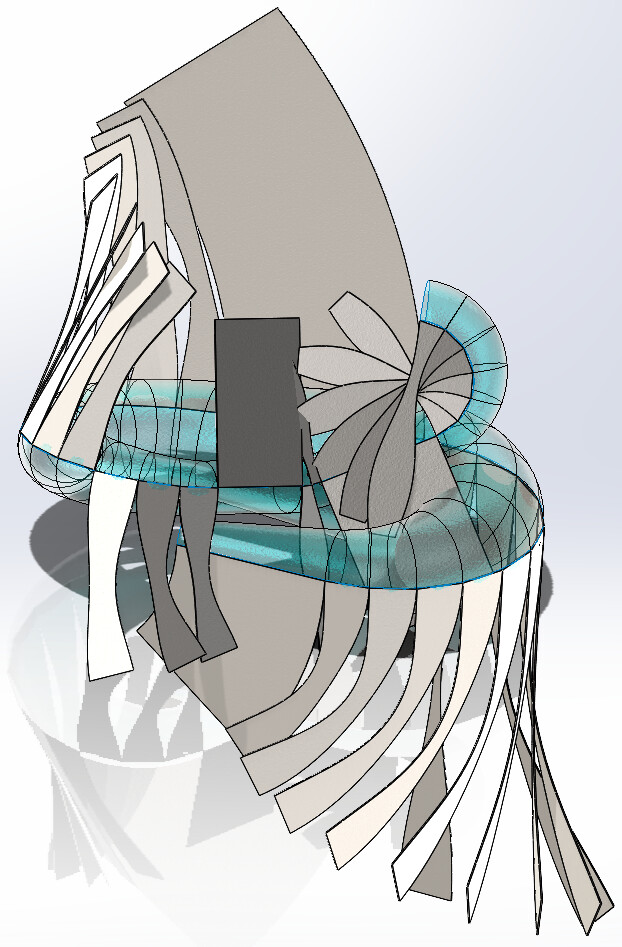
33 sheet metal elements that can be unfolded. It is at the foot of the workbench that the connections will be validated.
4 Likes
![]() I admit I wouldn't have believed
I admit I wouldn't have believed ![]()
And for the layout ![]()
1 Like
I answer myself
Yes, we can and can take out the bodies, well done @m_blt
Could you provide your part, I'm curious to see how you go from the initial form to the developed?
2 Likes
What I see above all is that @Burt_Munro is absent since his 1st post last weekend.
We still don't know the purpose of 3D drawing, simple creative hobby, school project, wish to make a house? If so, with what means...
The answer this weekend?
By the way, nice work @m_blt and I too would be curious to see the process to make it in sheet metal.
2 Likes
@sbadenis , @A_R
I guess
A cutting of the initial body into sections. Transform into sheet metal in what chronology in relation to the bending of its whole?
1 Like
Hello Fred78,
Thank you for your quick answer.
…@+.
AR.
Hello,
Good guess...
Nothing very complicated, just a Stakhanovist procedure:
- in the basic revolve profile, decomposition of splines in favor of 34 line segments (Sketching Tools > Segments);
- Generation of an open revolving surface (359 degrees), which has 34 sections.
- application of bending functions to the basic shape (surface of revolution) to obtain the final " snake " shape;
- creation of 35 3D sketches of the straight sections: open circles or generic splines depending on the sections, the mysteries of SW;
- for each pair of successive sketches, creation of the sheet metal section by the " Transition Fold" function;
- for each section, application of the " Unfold" sheet metal function.
It's laborious, but in the end quite fast.
I leave it to the specialists to draw up the unfolded sheets. ![]()
The SW 2023 model: Exhaust1.SLDPRT (9.2 MB)
3 Likes
The 2023 SW model
It's a mess, I don't have the functions