Hello, I have to draw the detail of a bending of a rectangular tube of 120mm wide by 150mm high. But I can't draw the 4 sides of the tube before bending. I'll give you my plan. Thank you for your help.
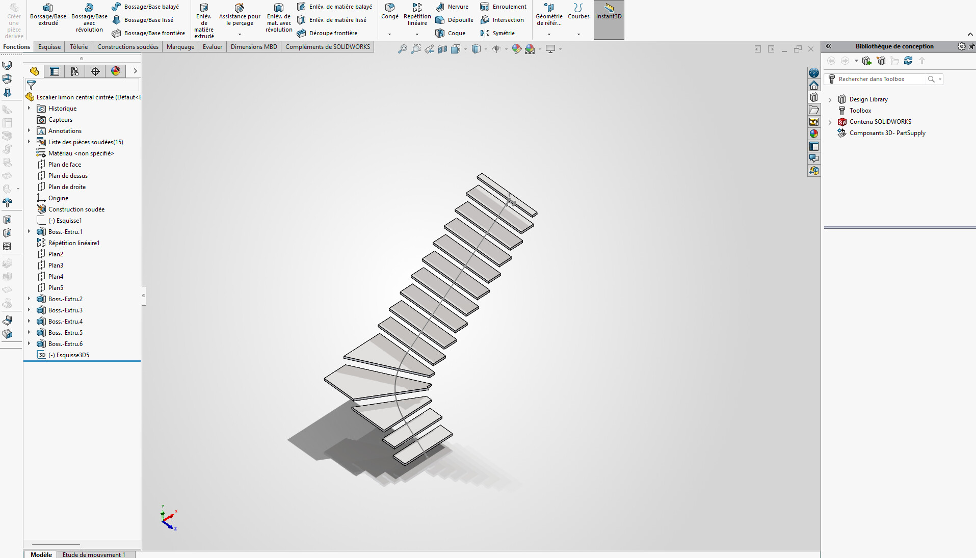
Arched central stringer staircase. SLDPRT (158.7 KB)
Hello @Benjamin_Diffels
Can you explain to me a little better what you want to achieve?
And can you provide me with a copy in 2022 version?
Hello;
Please specify the Solidworks version of the part offered for download.
(already higher than 2022... so I can't open it)
You should ask @ac_cobra_427 if he finds the original tutorial...
https://forum.mycad.visiativ.com/t/comment-deplier-un-tube-rectangulaire-mecano-soude/106754/4?locale=fr&lang=fr
I can't find it on the Visiativ platform...
The request lacks context, perhaps this?
https://grabcad.com/tutorials/how-to-flatten-hss-tubes-in-solidworks-fast-and-easy
… The wording is strange: 4 sides on a tube???
In fact, I have to make a part of a central stringer bent. But making a rectangular tube curved is not possible. So, it's better to make 4 flats bent to form a curved tube. And with the help of the program have the details of each dish. This is a SolidWorks 2026 release.
A 4-sided tube... And making a tube bent is not possible, so we make 4 flats bent to form a tube.
Bending the rectangular tube can be done but it deforms it quite a bit (and therefore changes its resistance).
You can do a 3D scan of your 4 sections: this will give you a geometry but depending on the curves of the scan it will not necessarily be feasible either (if all the radii are in the same plane it should be OK, otherwise you will probably have to cut / join the sheets)
Hello,
For my part, I will make the 2 vertical faces (inside and outside radius) in sheet metal, nothing simpler ![]() and then make the horizontal sheets in overlap with a quarter/quarter assembly for welding. Do the dxf for the laser and that's it.
and then make the horizontal sheets in overlap with a quarter/quarter assembly for welding. Do the dxf for the laser and that's it.
P1TEST. SLDPRT (136.8 KB)
Pa managed to open your room (future version)
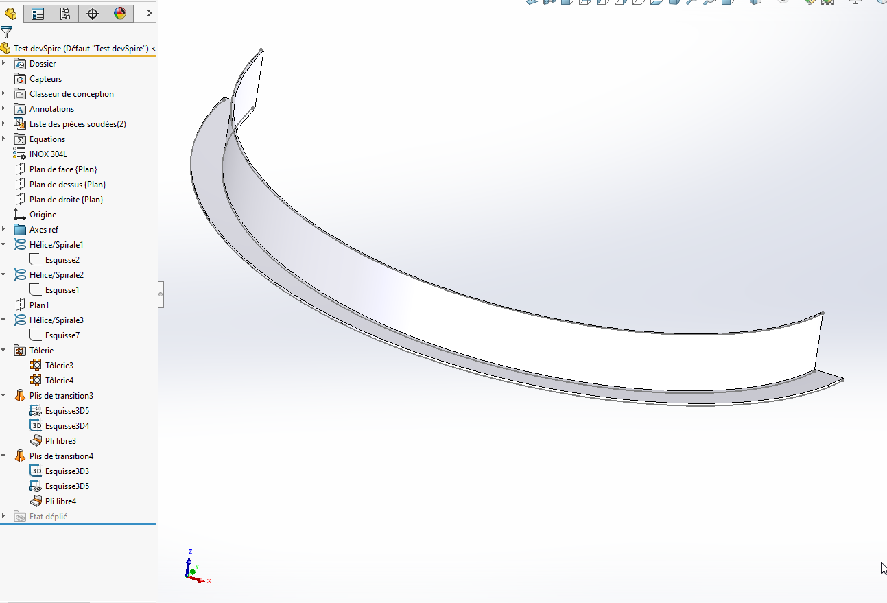
Here is a principle piece to render this in sheet metal. (SW2023)
Test devSpire.SLDPRT (420.6 KB)
For the sketch construction→ Propeller (x2)
We open a 3D sketch, select the 1st helix and convert the helix into a 3D sketch.
We make a 2nd 3D sketch with the other propeller.
Then selection of the 2 3D sketches and selection of sheet metal, transition bend (Formed option)
Given the description (bending) and without being able to open the file, I couldn't guess that it was a debillard operation (bending on 2 simultaneous axes)
With the winding function wouldn't it be easier?
But I would have to see the play!
Hello @Benjamin_Diffels ,
Below is a proposal for modeling the stringer in the form of 4 sheets forming the desired rectangular straight sections of 120 x 150 mm:
- creation of a 3D spline defining the general shape of the silt (yellow color);
- generation of the 4 faces by surface scanning of the sides of the section (orange color).
You must use the " Specify a direction vector" option for the torsion of the profile, by selecting a vertical segment; - creation of the 4 faces of the stringer in the form of sheet metal parts (turquoise color);
- flattening of the faces of the stringer (pink colour).
This result can also be achieved by activating the " unfolded " state of the sheet metal faces...
Please note: these faces are left-handed surfaces, so they cannot be folded. Flattening is approximation.
The visual quality of the result depends strongly on the initial spline of the stringer. You need gentleness... ![]()
![]()
![]()
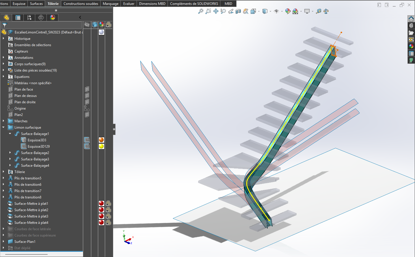
EscalierLimonCintre0_SW2023.SLDPRT (1.1 MB)
1 Like
@m_blt
Top but personally I would have avoided the spline to have something foldable for the top / bottom of the profile.
Let be a 3D sketch with lines and radii
Let be a composite curve
All spline can be decomposed into straight and radius. By relying on the spline for example.