Hello Solidworks in sheet metal mode gives me problems to keep the flattening of an elementary profile valid... Let me explain, I have a junction profile that requires the creation of several plies on the edge but these have inverted rotations (it's not a difficulty if you keep the same bend orientation with a still positive angle):
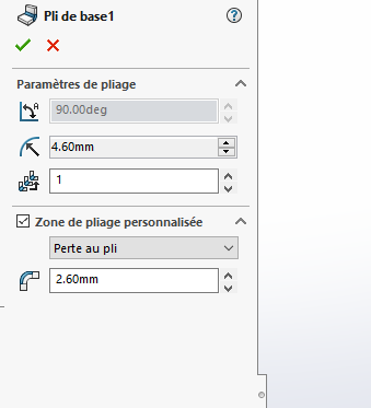
My configuration in parameterization of a 2 mm sheet
a 16 mm vee (compliance with the factor 8 of the thickness of the sheet, Amada abacus of the workshop machine park) So I have entered an inner radius of 2.6 mm, it generates an outer radius of 4.6 mm, but if you have a profile that requires a reversal of a bend it goes back to one with a very low and fixed inner radius, depending on its profile generation we change the profile corrector a bit like in numerical control, The inside becomes the outside in relation to the neutral fiber of the sheet. If I edit this radius in quotation for the corrected then the flattened function is inoperative, do you have a solution to keep the function active, thank you in advance. Spectrum.
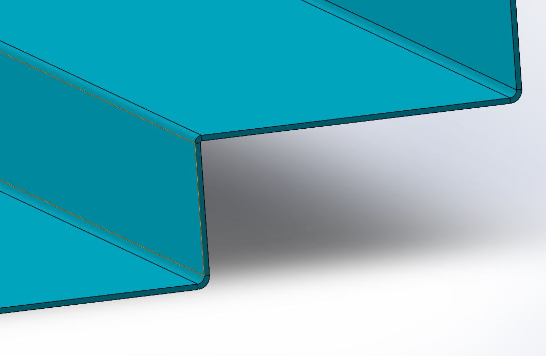
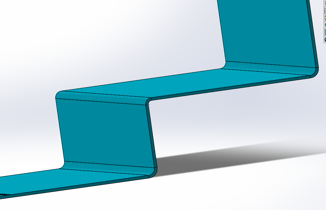
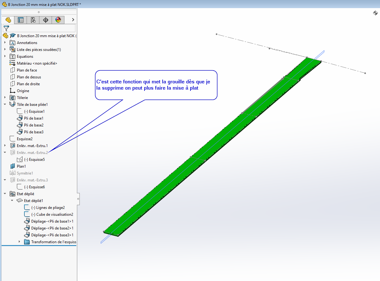
So here are the two parts, one made with plies on edges and the other with the sheet metal mode also but with a fiber and therefore a generation of the sheet in step two, it's faster but when I wanted to assemble ... I find myself with an incorrect inner angle in relation to my need, if this is the function I will bow.
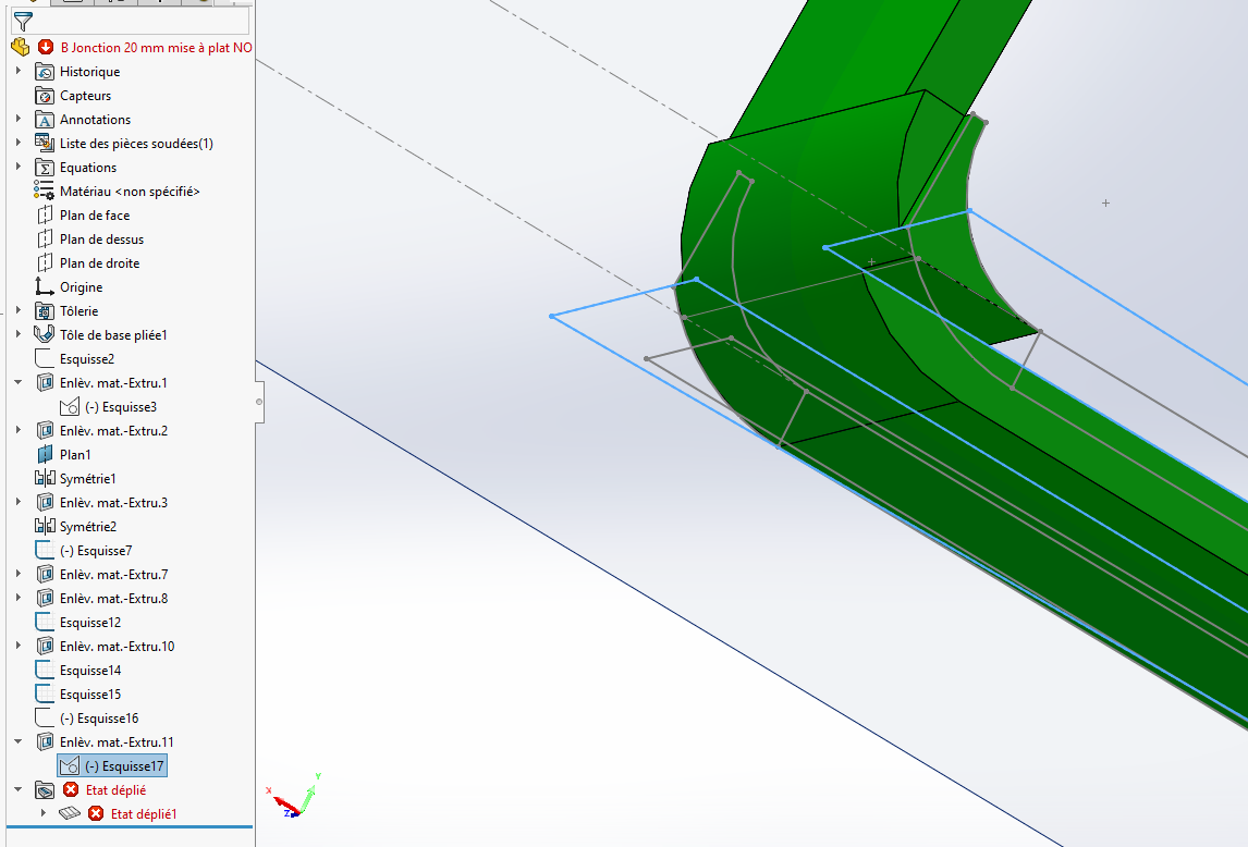
And in the case of the variants of this part where I find myself interfering with an already defined fold to make a second removal which therefore overlaps, I lose the flat function.
I can't open the file because I'm under 2016 at home, attached is a part I made and I'm having no problem reversing the sheet metal settings unless I have mail understood the problem.
Our eminent colleague @ac_cobra_427 will give you advice on the use of Bent-base sheet and also on the precautions for modifications by material removal (in other words, work flat for material removal or on the bent part as you did)
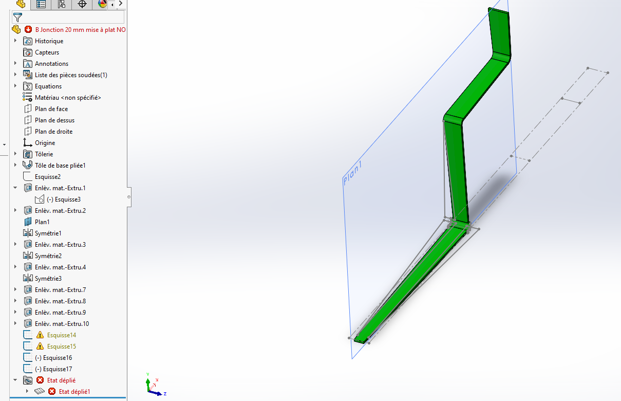
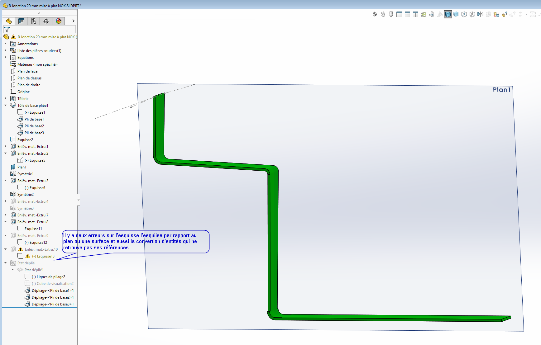
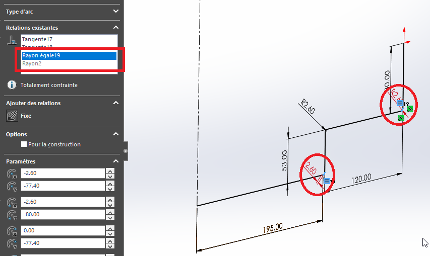
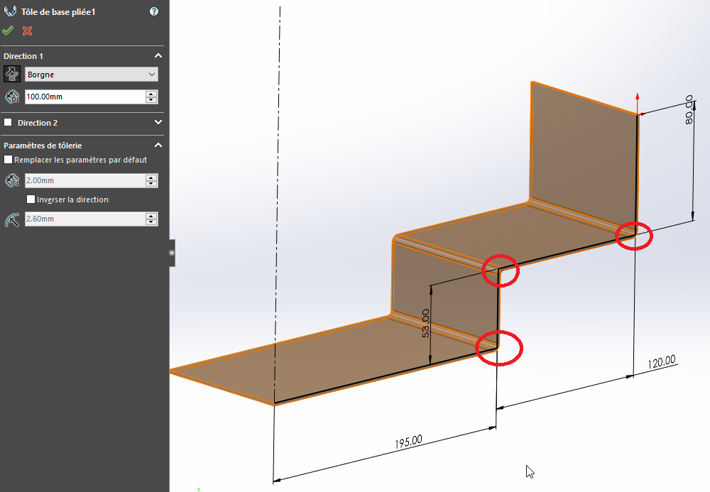
For the piece " Cheneau galva..." ": it is not the sheet metal parameters that are the problem, but the Sketch1... This sketch used by the " Bent1 Base Plate" function has 3 fillets, probably created in the same sketch function. They are therefore assumed to be equal by SolidWorks (2.6 mm), which is confirmed by the " Equal Radius16 " and " Equal Radius19 " relationships.
In principle, only the radius of the first fillet is dimensioned by SolidWorks. Forcing the radius of the other two results in these forced dimensions being assigned the " Controlled " property, and the values assigned to them are not taken into account. The dimensions appear in a different colour (in red in the figure above: relations " Radius2 " and " Distance12 "). The solution: simply remove the two "Equal Radius" sketch relationships and dimension the values of 3 radii, at 2.6 or 4.6 mm depending on which side the sheet thickness is.
A simpler solution is to leave no radius in the sketch, and leave it to SolidWorks to create them itself from the default settings of the Sheet Metal module. He knows how to manage the inside/outside side of the fold... They can always be modified later by editing the " Basic Fold" function.
And a proposal on the same principle for the part Junction element, with an overall material removal on the part in the bent state. Unfolding without problems... B Jonction_1.SLDPRT (121.0 KB)
Hello, thank you I didn't know it's interesting to let the module work in its place. I will now resume my sketch lines with inner and outer folds without any problem.
Thank you I wanted to adjust my cutouts from my assembly for not a good idea... I'm losing references. Thank you for the time spent understanding the anomaly and resuming the operational review.
I need to progress and observe more the sketched relationships, I had just realized that my non-Ok radius by changing sides was fixed and not modifiable, thank you for the explanation I archive your explanations, have a good day to you.