Differences between beam / shell / volume

Hi all

Will anyone be able to explain why there is a difference between the results of a simulation in beam mode, in hull mode and in volume mode?

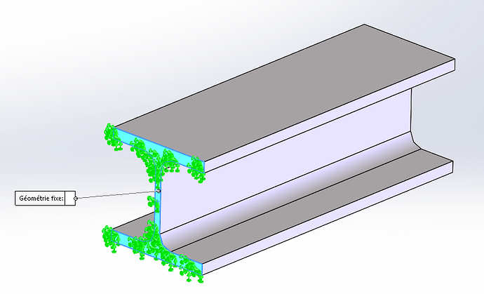
For the example I have a HEB100 of length 800.
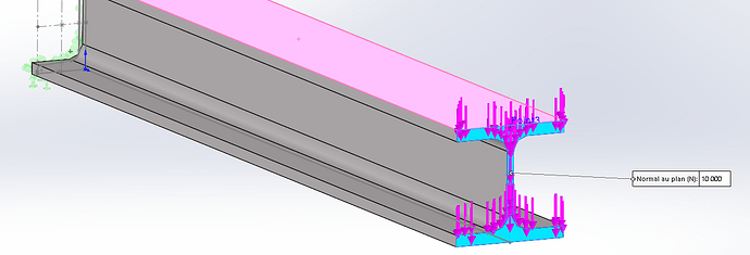
it is recessed at one end and I apply 10,000N on the upper side


.

In volume mode I get: 91.88 MPA
In beam mode I get: 88.98 MPA

Personally the difference doesn't worry me, and I would justify it by the simplified side of the beam mode (which would not take into account holidays for example)

Second question: Is the method correct?
Which of the two methods is the right one?
I am well aware that the model studied is VERY simple but I would like to know if we can trust the hull mode on more complex models?

Thank you in advance for your answers.

1 Like

Hello
I think the difference may come from the mesh (from my memories of training) but the comparison is the subject are interesting

1 Like

Hello

Here are some rules without being stunned

1°) the hull mode is not suitable because it is reserved for thin sheet metal parts or other thin parts that are a little complicated (this is to facilitate the meshing on thin parts).

2°) The beam mode has a particularity to be taken into account, which is that the beam must never have indentations (such as a recess on a wing).
The beam method is well suited (because simplified mesh and large mesh without seams in the corners and ratacoins in convoluted volume parts). For frames with homogeneous beam elements, the beam mode is very fast and energy-efficient due to the very large mesh elements. In addition, there are some complicated things to manage with IPNs.

The volume mode is rather to be preferred as soon as you have machining, gussets, holes and reinforcements that are a little special. I find the volume more practical when you have remote charges or stability conditions to think about.

Personally, I only did volume because with powerful computers the time of meshing and post-mesh calculation are not very important.

If @m.blt goes through this he will explain it to you in detail and quality.

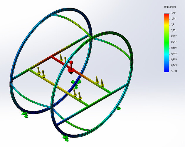
Here is an example of a frame on which is placed at an angle and not centred on the main axis, a localized load (yellow arrows) of 1,600 lilos in rotation of 4 revolutions minutes. The whole rests on another frame with rollers, two of which are servo-controlled on a geared motor.

1 Like

Hello

Just like our national @Zozo_mp (who seems to be a little bothered when he retires ::wink: )

The beam mode is rather intended for general calculations such as metal structures (but as a result we don't really know what happens at the junctions of the beams).

There is also a way to do mixed studies now (like the majority of beams in mesh beams and the details of the mesh junctions in volume). This allows you to have a model that is not too heavy (thanks to the beam elements that make you 80% of the volume of your model with a few knots) while being detailed enough in the critical areas to have a realistic result.

You will also notice that your results will be different depending on your mesh size

1 Like

@froussel
There! I'm just in periscope immersion waiting for my medal to be received.

After that, it's the depth bar at full speed, then dilution in the immense ocean of knowledge.

Blup blup! :anchor:

1 Like

Hello. " UpperE " side takes an " e " at the end. I don't really understand your image because, the blocking on one side: ok. But then your load only seems to be applied at the other end. It looks like you're not selecting the top face. The forces are applied at the end. Or your statement is poorly explained.

Hi all

It actually confirms what I thought and it clarifies some points that I didn't necessarily know how to explain.

Thank you for your answers!

A+

Hello to you,

Allow myself a few additional information.

The different modeling solutions that are available to you are:

1- Beam mesh, this theory only applies if the length of the element is greater than 3x the largest dimension of its cross-section. A priori this is the case here, and it is also the method I will use for its simplicity/speed.

2- Shell mesh, unsuitable here because your profile is not of constant cross-section. With a square tube or rectangular tube you could possibly replace a beam with shells, which would allow you to better manage some recalcitrant connections with other bodies. But these are extra clicks that are not useful here.

3- Volume mesh, You will need a fairly fine mesh refinement, which consequently generates machine resources and additional computing time, in my opinion useless unless it allows you to " reassure " you.

4- Do a bending calculation on a corner of a table, in your case it takes less than a minute with a form and we find 89 Mpa and dust.

5- Use the " flex form" tool integrated into the toolbox, which in a few clicks will announce to you: 89.91 Mpa

Namely, that all these methods use hypotheses, so you have to be " on the right track "
And with finite elements, we only try to limit the margin of error generated by assumptions and discretization.

Be careful, in your sentence you say apply the force " on the upper face" of your HEB (a distributed force?), but in your screenshot you apply a concentrated force at the end of the beam. I'll let you check which one is the right one!

NB1: don't forget the gravity field either, which will create the weight of your element!

NB2: remote loading is very practical when you don't need to model everything and you want to avoid doing a force balance to bring the applied forces back to the place you are interested in. Here it is obviously useless.

I hope I helped you.