Hello
I am starting to use the fluid mechanics module and I have problems with implementation...
Basically, I want to find a characteristic of a plate exchanger. The calculation of the lmtd.
I have defined the associations of the modules (alternating) then I put in simulation, the fluid is distributed (see video below).
Has anyone ever worked on plate heat exchangers?
Have a good day and thank you in advance.
Spectrum
Editing the assembled digital model:
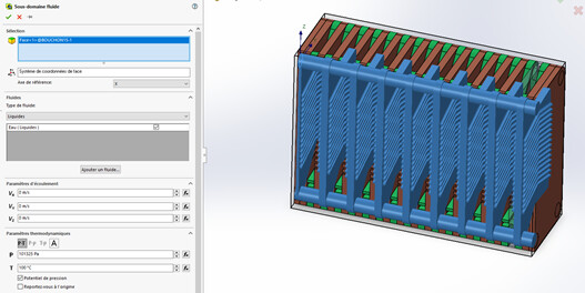
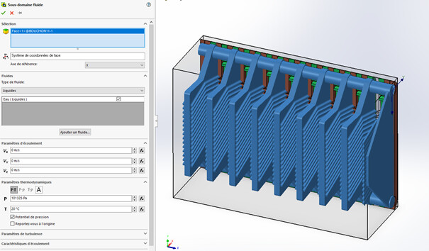
Two cavities are created:
One for the cold branch at 20°C
The other for the hot branch at 100°C*
The illustration below is for the hot branch.
The basis of the study is adapted to water subjected to an atmosphere.
Creating a Fluid Subdomain
Case of the cold branch
Equation OK to enter in the dialog box.
Plate Temperature échangeur.7z (3.1 MB)
I made changes to my definitions without the LMTD.
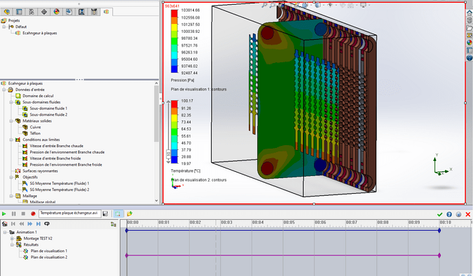
A capture of the fluid representation (temperature) on the exchanger plates.
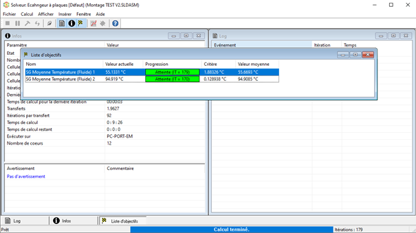
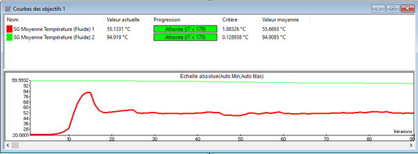 ! Basic étude.7z Simulation
 (188.9 MB)
Hello
I have a problem with the fluid path on the hot branch, the upper part and the lower part communicate before performing the entire plate exchanger.
I get these results but I have a question about the placement of the flows, the hot fluid migrates from the back to the front on my negative Z-axis, I am connected to the closing plate and the fluid moves in the intervals of the modules.
I am not sure that the study will be properly implemented.
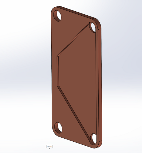
To implement a beginning of the influential parameters, I think I will base myself on the core of my exchanger plate machined on both sides.
I have a sandwich construction with my Teflon dividers.
By launching a design study, I can integrate the thickness of my machining to observe the repercussions on my exchanger.
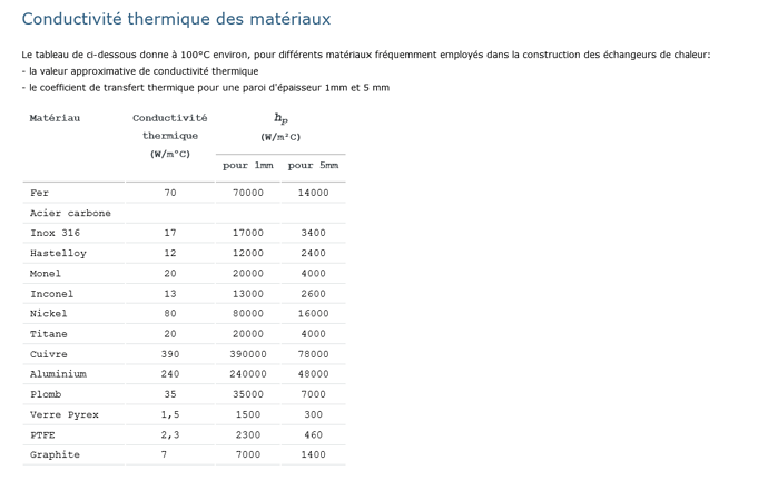
Material Copper 390 Thermal Conductivity Plate
Thermal conductivity PTFE 2.3 intermediate
Analysis of the simulation results:
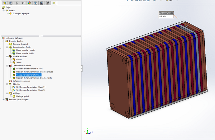
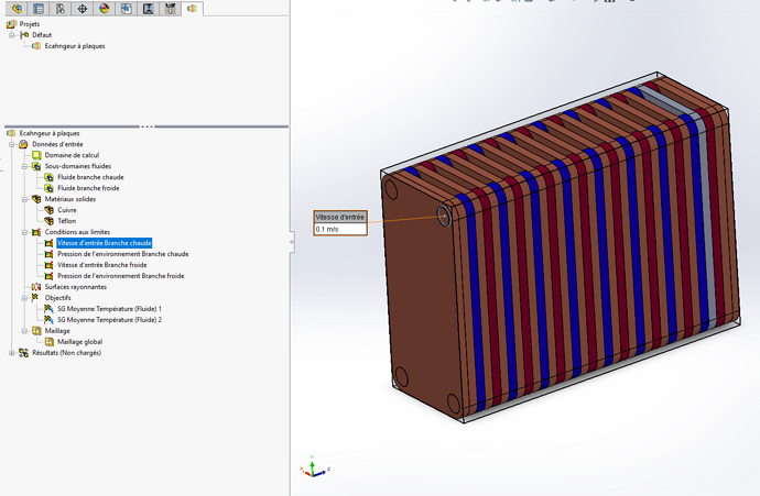
Hot Branch Input Speed
Hot branch fluid
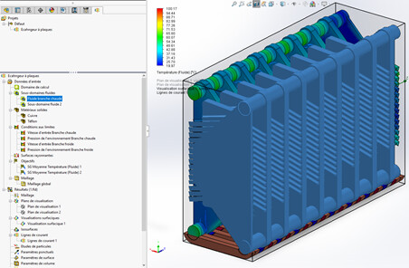
Cold branch fluid
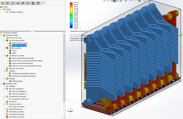
Cold Branch Inlet Speed
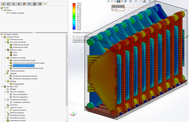
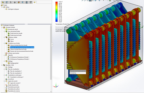
Pressure, environment, hot branch
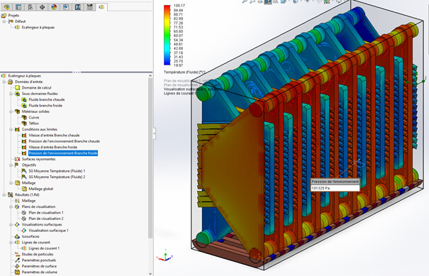
Pressure environment cold branch
My basis of study is this source:
I have carried out machining on both sides, their model is one-sided
The simulation gives an image of the heat transfer RAR copper.
Their seal is very weak, so I'm going to change this thickness of the PTFE spacer.
modification V3.pdf (201.1 KB)
1 Like
Hello @spectrum
Where are you with your study because some points in the images trouble me.
Whose:
The absence of baffles in the plates
The fact that the exit of the initially cold flow remains cold, a bit as if you had not plugged the exit part of the inlet side. There is no inlet at the bottom of the cold part, there is only one inlet at the top and only one outlet for the heated water. I have the impression that there is a bone in the power supply to go fluid to reheat.
Also specify whether you are working in co-current or counter-current.
What do you think?
Kind regards
Hello Zozo_mp,
Basically, I'm going against the grain
Entrance of my cold branch
Entrance of my hot branch
I have the impression that hot plates don't transfer effectively to cold plates...
I have a 50 mm spacer for 50 mm plate thicknesses.
If I reduce the spacers, I reduce the fluid cell but it is in contact with the 50 mm fixed plate for its unmachined part, my machining is on both sides (good or not well) on exchangers marketed on the video only one side of exchange.
In design study I will start on the influence of my PTFE insulation.
I discover and I find the visual tool, after getting something verifiable by a physical object is my idea.
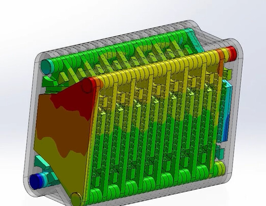
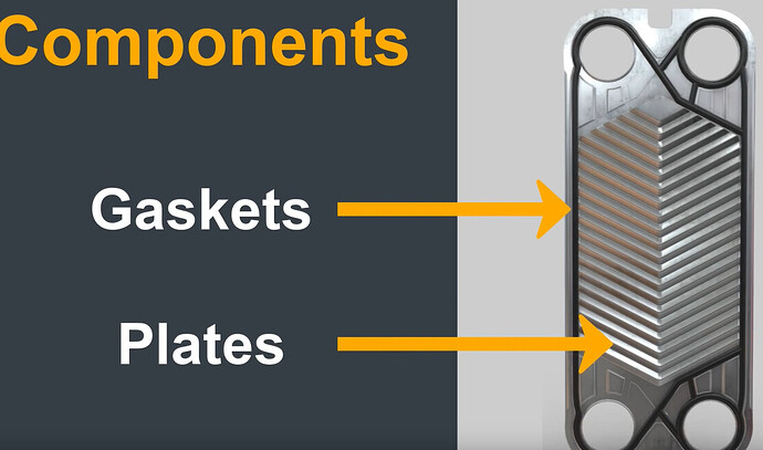
That's an exchange on a manufacturer's plate.
Thank you for the message, I will continue.
@spectrum
A few remarks! (For the following I only mention a single-phase exchanger (check that your supplier's plates are for single-phase. I don't have any knowledge about two-phase
1°) Are you sure that it needs 50 mm of thickness for me it's closer to 0.5 to 1mm
2°) for machining on both sides it is actually done by corrugation which in good French means embossing (as for corrugated cardboard). As a result, embossing increases the contact surface and causes a turbulent flow that greatly increases heat exchange.
Embossing causes turbulation for both sides (of both flows simultaneously).
3°) what matters is the pressure and the flow so that all the elements are supplied to 100%. If there is not enough pressure, the liquid will not go all the way, which is worse in counter-current flow.
You will tell me that the manufacturer's example does not have a waffle but since you are understanding how it works, it means that the diameters would not be in question, because defined by your supplier, but that it would be the pressure.
This also means that the volume that must change temperature is too large compared to the time of parking in a plate (in addition without or with low turbulation.
I won't say more because it's largely out of the vocation of the forum which in principle focuses more on the features of SW than on the design of the parts, even if we are not stingy to help a student 
Kind regards
Hello zozo_mp,
I will reduce the gap between two plates and then vary the speed of the fluid to obtain a compromise between the exchange made in relation to time.
Thank you for the comments and advice, I find it nice to be able to exhibit on the forum and benefit from the feedback experience on SOLIDWORKS features.


