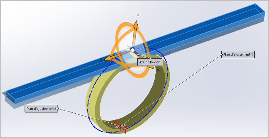
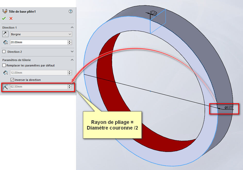
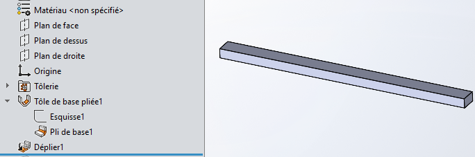
Why not a very simple solution, which remains to be validated. The " Insert> Functions > Bending... " of SW makes it possible to deform one or more bodies, by imposing a geometric transformation on them. The " Bending " option consists of a deformation by rotation around an axis, parameterized by an angle. A straight (blue) rung can thus become a circular ring (yellow).
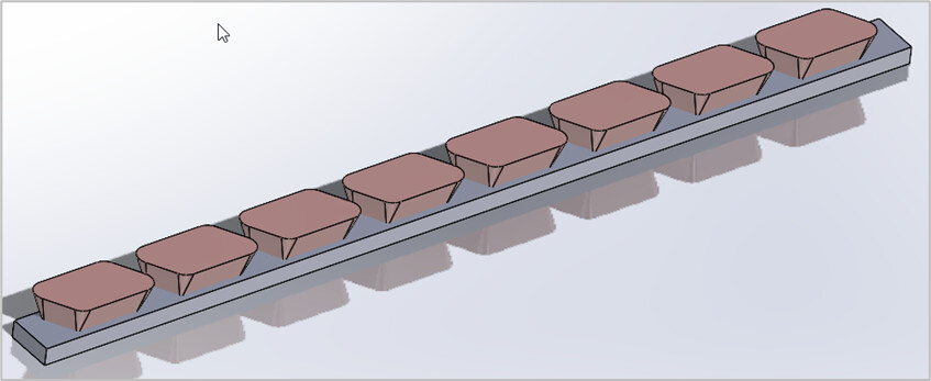
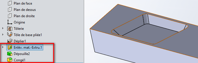
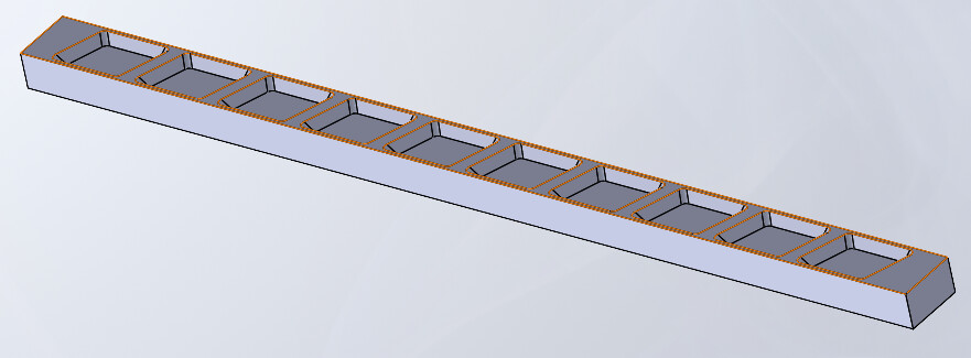
An extruded body, with a constant draft of 20 degrees, will undergo the same transformation. The same goes for a repetition of this body.
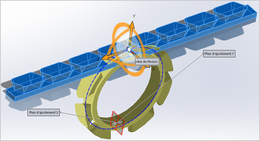
After bending...
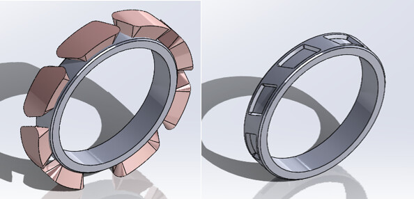
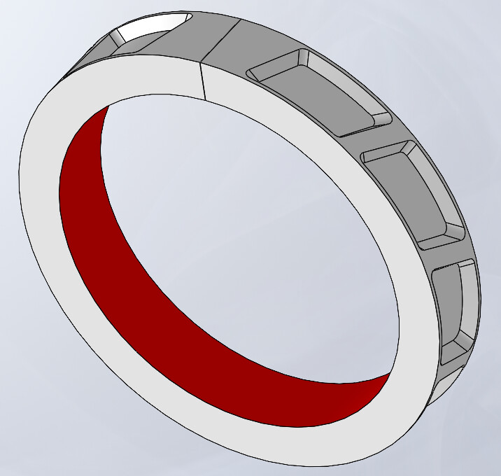
The final result, without and with material removal by the " Combine " function.
The accuracy of the geometry obtained depends on the geometric transformation by SW. It is easy to verify that the straight bar does indeed become a cylinder. But it is more difficult to ensure that the constant 20-degree draft of the bodies of the definition remains a 20-degree draft of the normal after bending. Visually, this seems to be the case. The dimensions of the " rectilinear creation" will still have to be defined in order to obtain the desired dimensions of the " circular bending" version.
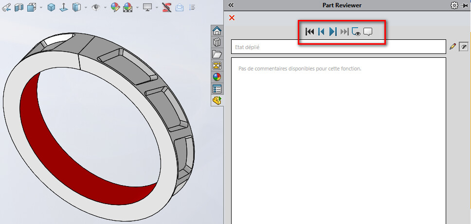
Nb: I just realized that the "streaming playback" option has completely disappeared from the " Part Reviewer "... Sniff It was however very practical to make video captures of the design of parts (on the other hand I didn't use it much, and if it happens this option has disappeared a long time ago).
Rather than using the bending function which is (or was at the time a gimmick) I will use the winding function on a diameter.
You do the series of shapes after making your cylinder and you wrap around your cylinder so that you can drive I think more easily and in a less empirical way.
But I'd like to see your tree structure and your piece to see the weight. If this is the form you want, I think that the previous method I proposed should also work. THERE you need a calculation to define the lengths of the shapes but nothing insurmountable
You should know that if you do machining and you program via SW, you have to pay attention to your 3D design method because the software when it breaks down your 3D to identify the Machining Phases is based on your design. But now I'm afraid he'll face you with weird stuff (but they must have progressed on these tools)
FYI I tried the shape tool it doesn't work or maybe by fiddling so I gave up