As the title says, I try to extrude a surface via a sketch, at the normal of a cylindrical surface, but with an additional angle it could be a volume or a removal of material
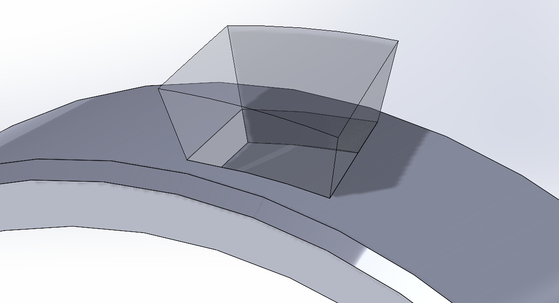
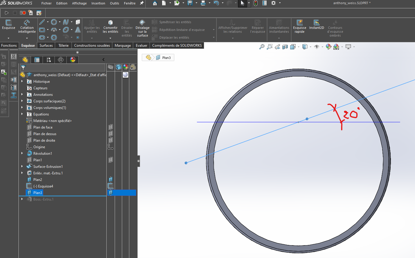
This shape would have to be extruded to the normal of the cylinder with an angle of 20 degrees more outwards (the created body enters the matter)
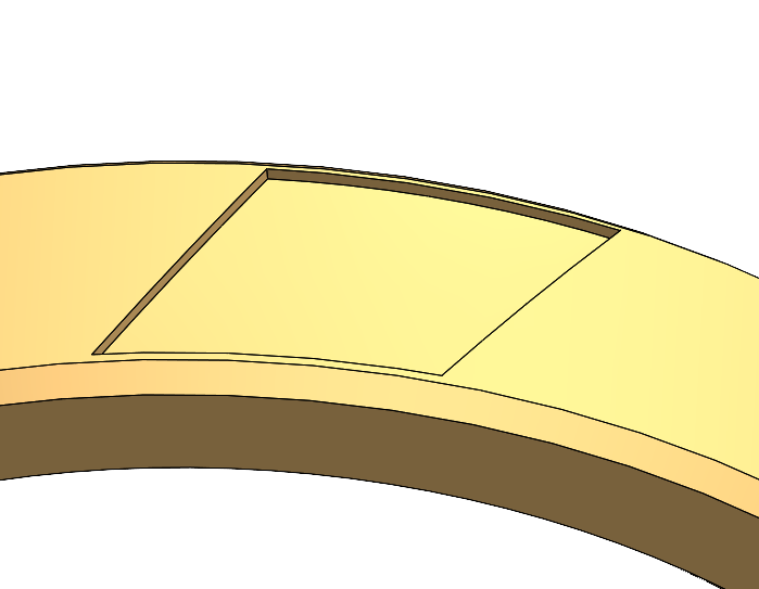
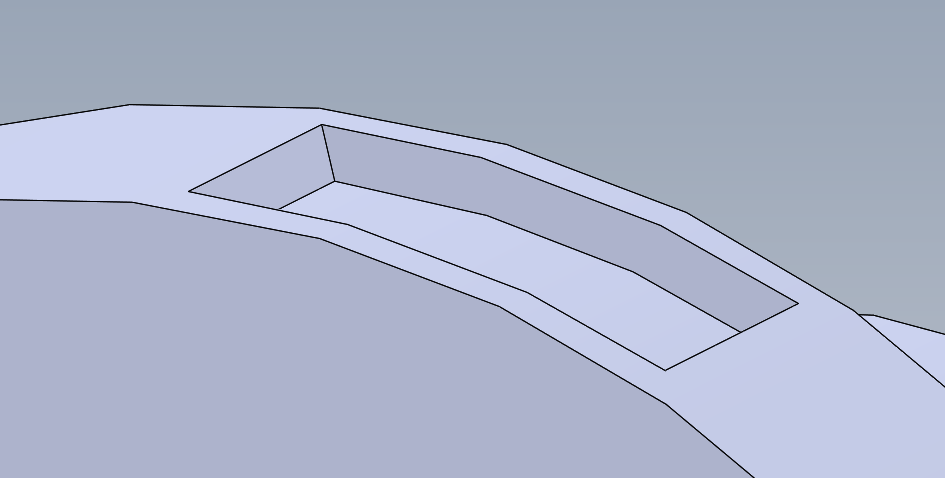
and the end result must be a pouch (stamped)
It seems easier to me to create a volume body and then stamping it in the part than to remove the material directly
Have you ever done this? What would be your solution?
This description is reminiscent of a draft angle... True or false? It is sufficient to use this property (draft) in the creation of the extruded volume, and to define the extrusion limits by two cylindrical surfaces, which are then hidden.
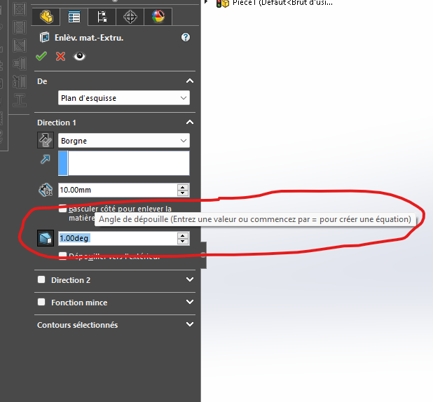
YOU have the choice in the extrusion function, you have the possibility to create draft angles
Or with the help of two sketches you create a body that you subtract from the main bodies
Or by stamping
But it takes longer, you have to create a tool with the right dimensions, and create a library of stamping tools, define your part as a sheet metal. In short, it's a hassle for the little you want to do, and it's like subtracting a body
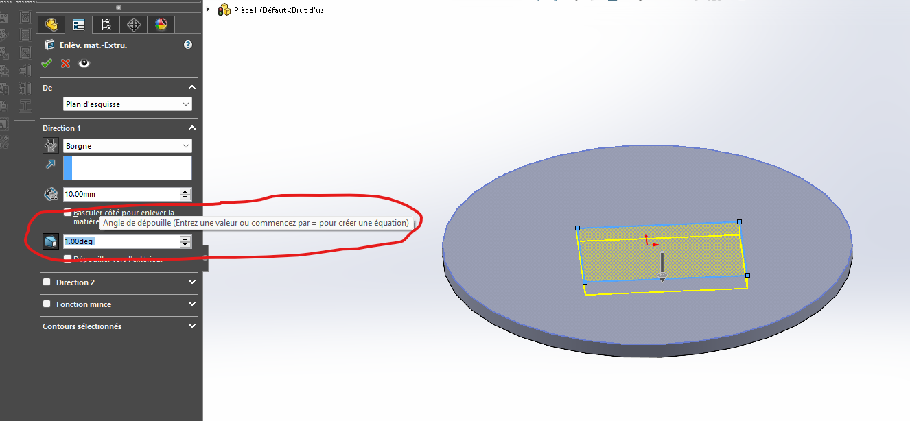
yes it is indeed a draft, but if I apply a draft, it takes the angle with respect to the given extrusion direction, while I want my extrusion to be at the normal of the cylindrical surface, I would want a draft on a normal extrusion on the surface
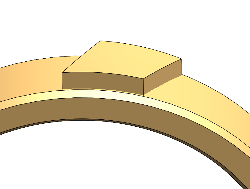
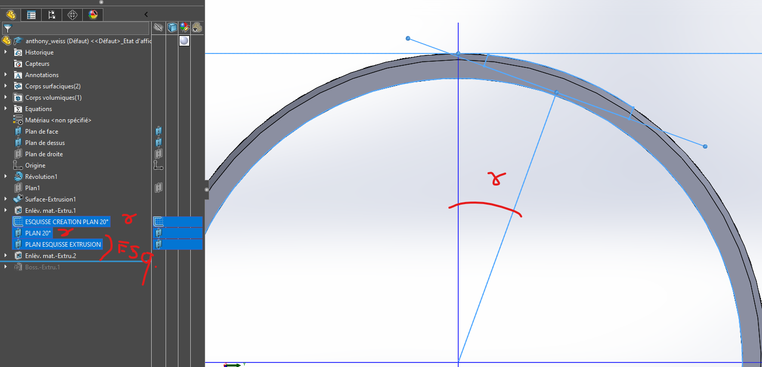
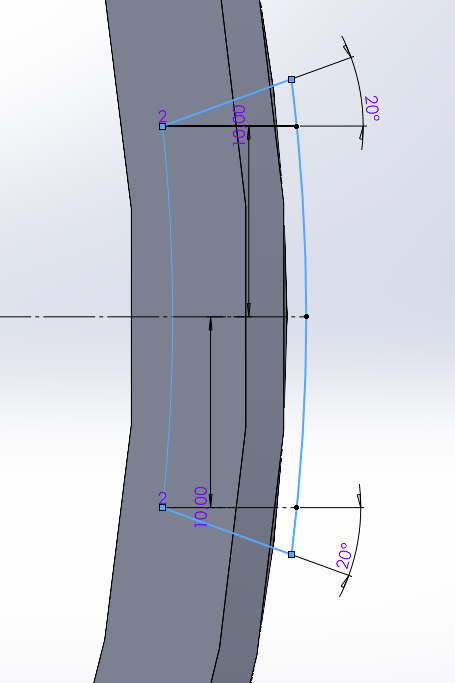
Here's an image that will explain better than words Here I am doing a normal extrusion to the surface (so all my surfaces are oriented towards the center of my cylinder), but to this I would like to add a draft of 20° compared to the normal, and not in relation to a plane direction The diameter of my cylinder can evolve and therefore the angle of the normal too, the pattern is always the same size.
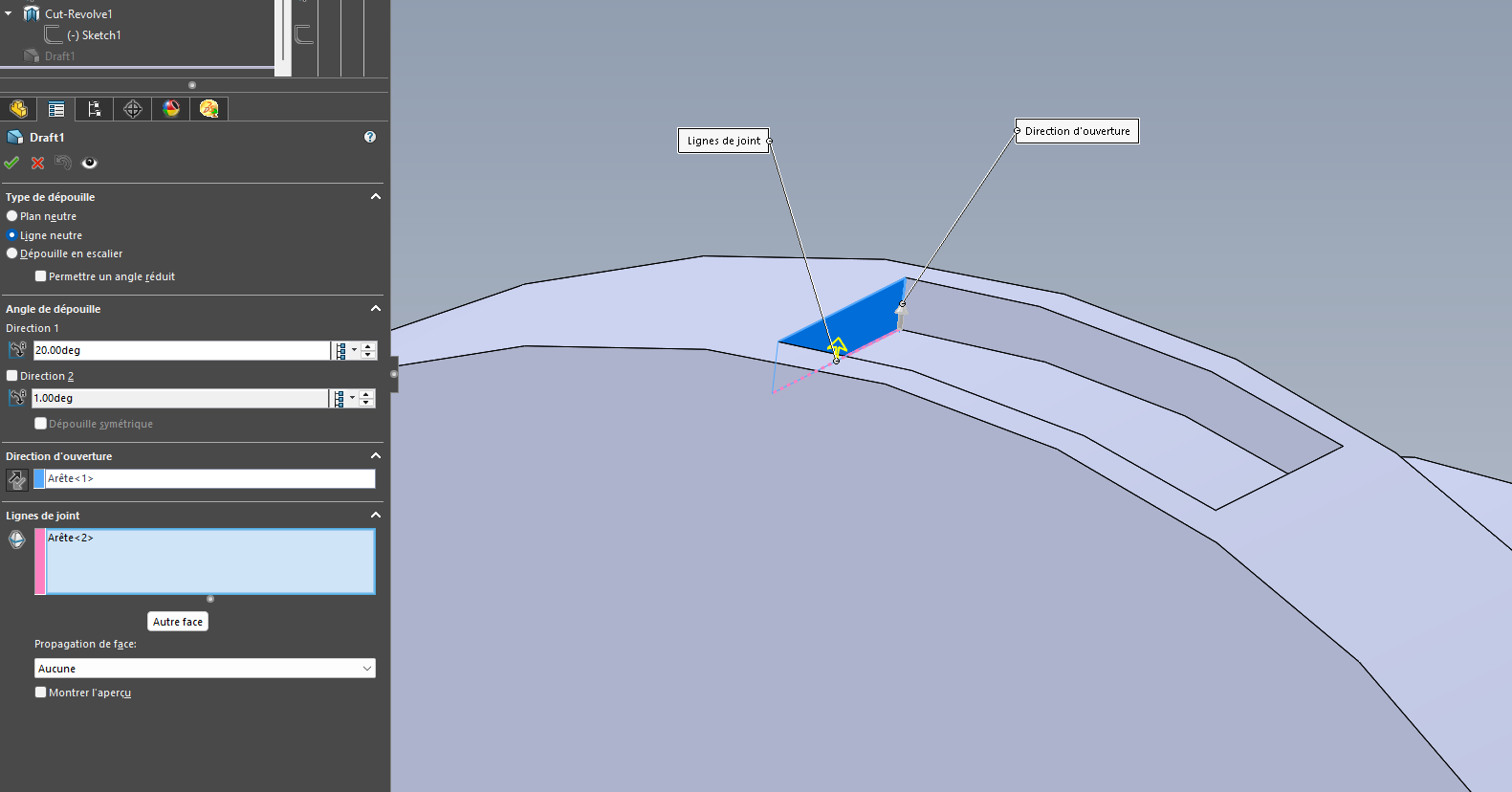
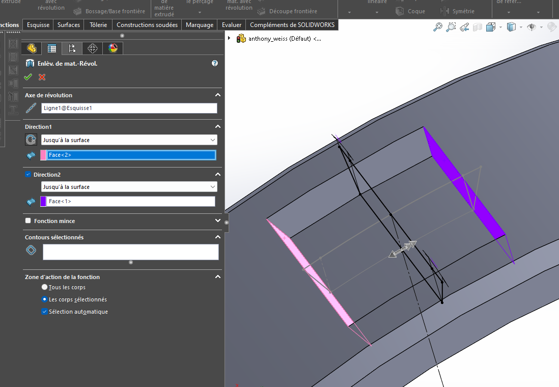
I think it is enough to generate the material or the removal of material by revolution (to obtain the initial faces normal to the cylindrical face), and then use a neutral line draft function with an angle of 20° on the faces that require it.
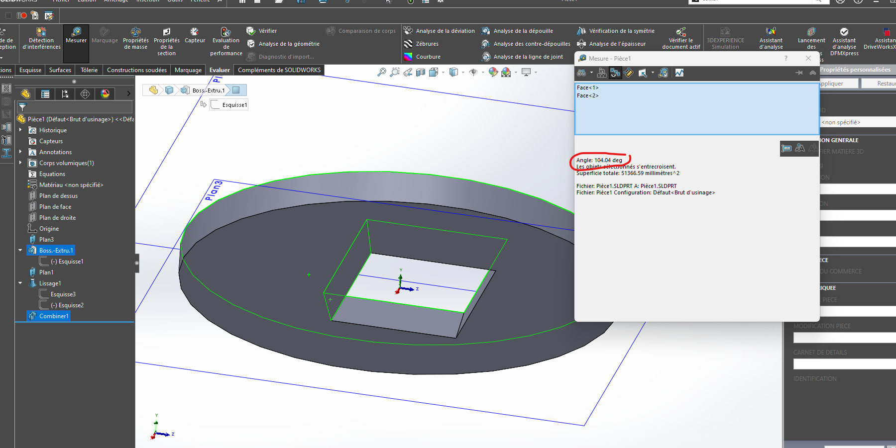
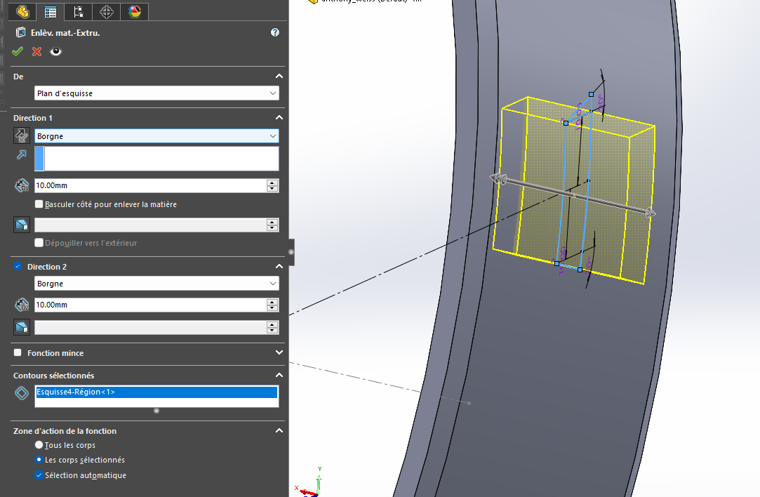
I don't think so, if you give a direction, for example an extrusion of a rectangle like in your case it will make the drafts in the two opposite directions. Try to do it, and make a screen print so that we can see what you get.
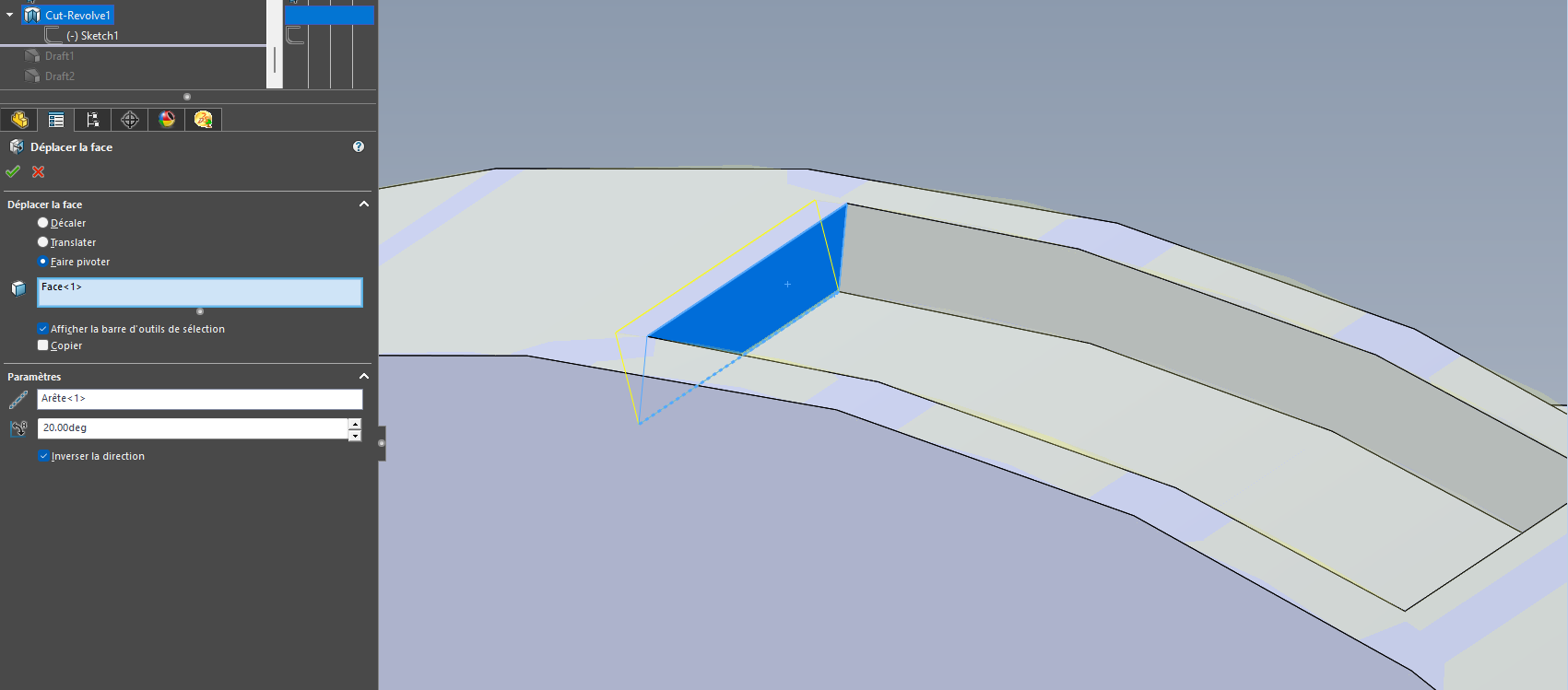
This is what seems to me to be the closest to what I would like, but once again you have to give a direction, something I don't want, because opposite the pocket, the angle is not good. I think the option I want is not yet in the software.
I thank you all for your ideas and different approaches, I will try to be inspired by them to try to find a solution and I will come back to update the subject if ever
Quote: I think the option I want is not in the software yet.
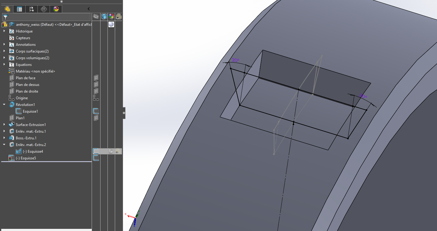
And given the complexity of the problem, I fear that it will not be available for a long time. I propose below an approximate solution, in 6 steps:
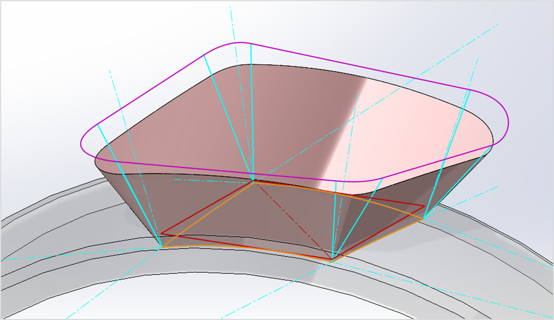
Creation of a flat sketch (in red) that defines the outline of the volume to be generated or removed: parallelogram to look like the first image of the post;
The sketch is wound on the lower cylindrical face (winding function). The resulting curve is converted into a curvilinear outline in a 3D sketch (orange);
In this same 3D sketch, creation at the 4 corners of normals with a cylindrical face in the form of construction lines (turquoise);
Still in the 3D sketch, two segments are created from each corner, i.e. eight segments in total, of the same length. Each segment is at an angle of 20 degrees to the normal, and it is constrained " perpendicular " to the corresponding segment of the curvilinear contour;
The eight end points of the segments are joined in the form of a closed outline (purple). For want of anything better, by segments of straight lines opposite the sides of the lower contour, and by tangent splines in the angles;
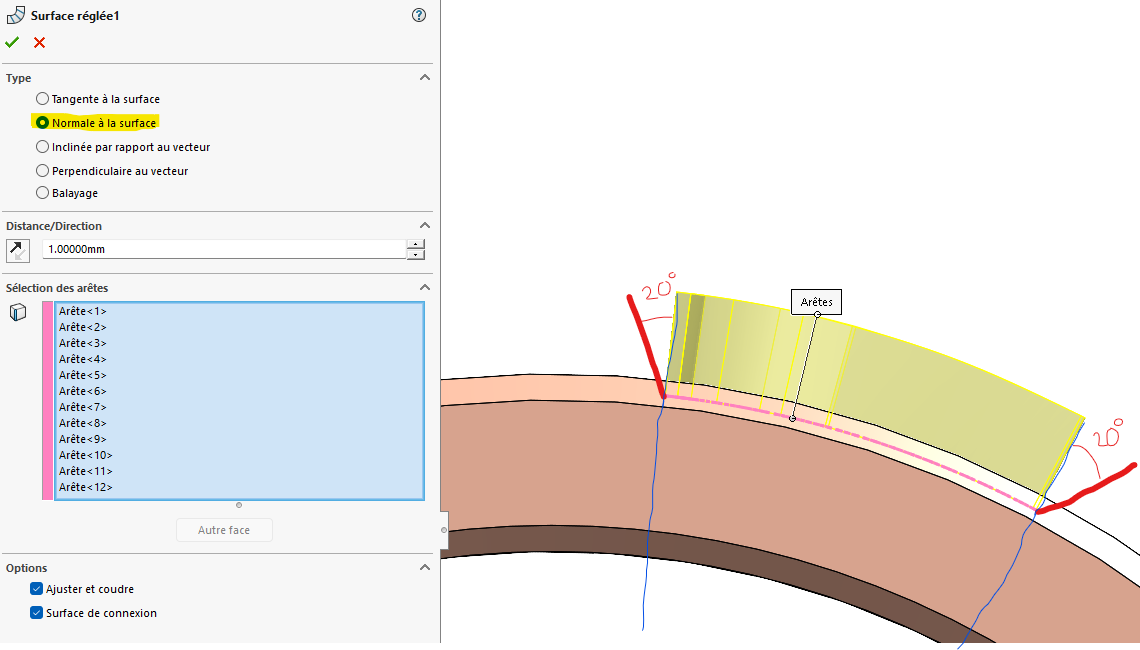
The outer surface is generated by surface smoothing with the two contours as profiles (orange and purple), and the eight segments as guide curves (turquoise). A few " Restrict Surface " and " Stitched Surface" functions later, the volume is generated.
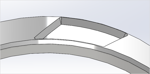
The result is an approximate response to the initial request, since the angle of 20 degrees is strictly respected only for the 8 guide segments. Also note some kind of cones in the corners, a solution to try to respect the 20 degrees. I don't see how else to do it. Below is the appearance of material removal.
The process is laborious, but if it is essential in the design... Model attached under SW 2022. anthony_weiss0. SLDPRT (212.2 KB)