Hello forum, In an assembly, why and how to release the " Move / Copy bodies " function which is currently grayed out and therefore inaccessible.
Thank you for your help.
SW 2025
If it is indeed this function:
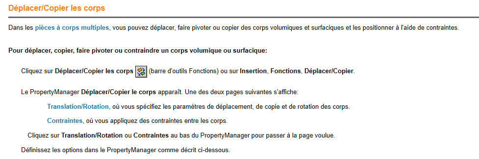
It only works in one room (multibody).
In an assembly, there are no bodies but parts or assemblies with constraints.
So to move it, copy, act on the constraints. Not with this function, which is normally grayed out since it is not available in an assembly.
3 Likes
Thank you sbadenis,
I have never used the " body " function!
In fact my assembly, following a wrong handling I think, is no longer aligned with the original trihedron!
So I am looking to realign the assembly on the trihedron, and thought "simply" to use, by mistake, the function move bodies!
What solutions are possible for this realignment?
Thank you
In general, in an assembly, there is the 1st part that is fixed:

The others are then constrained in relation to this fixed part or between them.
If this part is badly fixed the 2 original parts are not aligned for example, possibility to do right click free choose the 2 origin assembly and part to be fixed and add the constraint then right click fix again for example.
It is also possible to attach a different part than the one initially fixed if the choice was not the most suitable.
No fixed part in my assembly! I tried to fix and then release the first part to have the choice of the 2 assembly origins, but I didn't have a proposal concerning this choice.
As a result, I "snatched away" reorienting my first piece with the " Move with the trihedron " function. It's very approximate and I think not very conventional ![]()
There are surely 3 constraints of a part that fixes it in relation to the assembly. It is this piece that must be freed or reconstrained.
Hello
For my part, in general, I fix my first part deposited by constraining it with the origin of the assembly because my sketches of parts always have a link with the origin
1 Like
Same thing @Le_Bidule I select the 1st part and validate (which aligns the 2 origins) and at least the base is sound!
Ps: And I give the spanking for those who don't do that in my company! ![]()
2 Likes
Thank you for your advice that I will apply on my next projects. ![]()
But on the current one I can't find what is fixed and that generates this misalignment!
Hello @Patrick_GABLE
To identify the constraint responsible for your problem, you can expand the constraints in the FeatureManager and put them one by one in the deleted state (starting at the end) by trying to move the component between each deletion, until you manage to move it, it will mean that it was this last deleted constraint that fixed the component.
1 Like
What do you mean by 3 constraints of a part that fixes the assembly?
all my constraints are from room to room!
How do I "filter or search" a constraint with search criteria?
Hello Sylk,
This assembly has 92 constraints! Reviewing each constraint they are good from room to piece and I do not see the link with disorientation with the trihedron!
Hello
If you can, maybe by posting screenshots of your featureManager where we see the components and constraints developed we would see something that you would have missed.
Edit:
Oh and also, to move components in an assembly, besides the trihedron, the function is " Move component " in the Assembly tab:
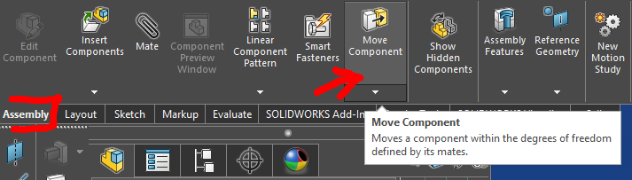
1 Like
Here are screenshots of the featureManager with all the constraints.
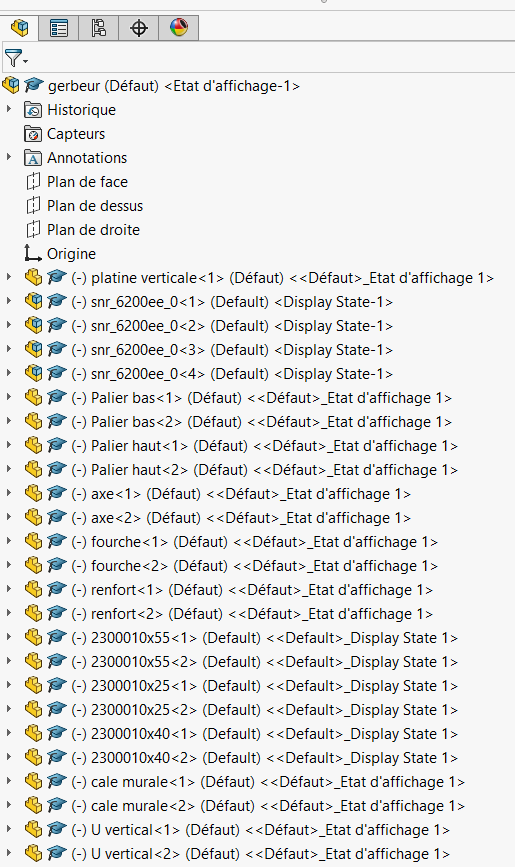
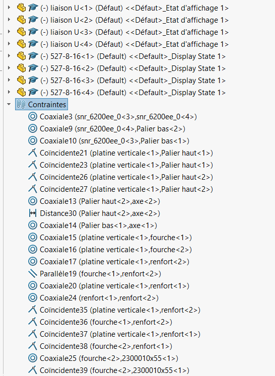
Thank you for your informed eye ![]()
Nothing seems suspicious to me.
On the other hand, I may not have understood your problem precisely.
So if I summarize what I think I have understood:
You have an assembly whose components don't have their planes parallel to the assembly planes, and when you use " move with trihedron " you see this trihedron aligned with the assembly planes, when you would like to see it aligned with the component's planes to correct this misalignment. Am I wrong?
I understand that you have something like this:
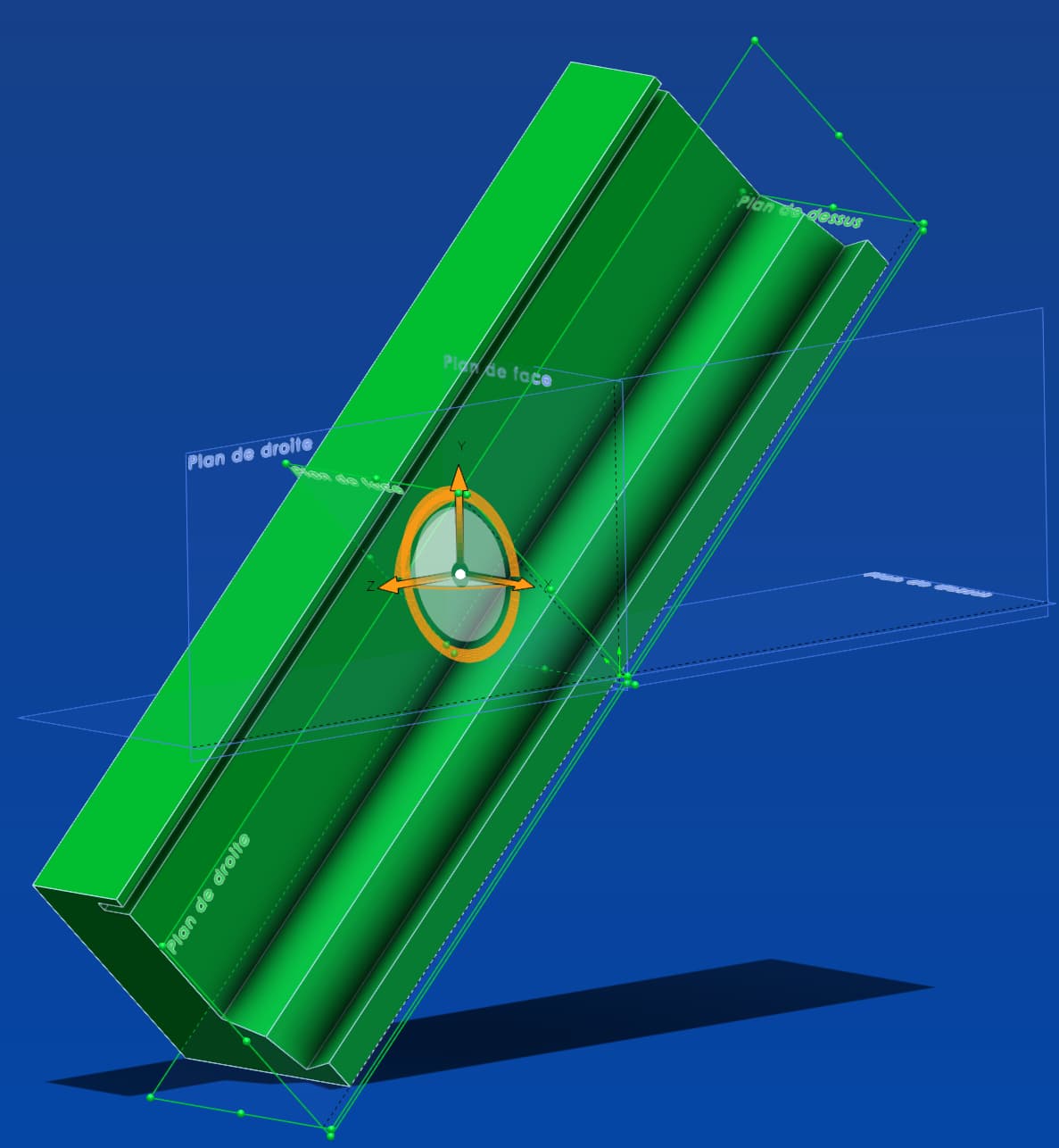
The planes in green are those of the component. The blueprints are those of the assembly.
If my interpretation of your concern is correct, then the easiest way is to simply create 3 new temporary coincidence or parallelism constraints between the basic planes of the assembly and the basic planes of the master component. In other words, 1) front plane of the component parallel to the face plane of the asm, 2) high plane of the component \\ high plane asm, and 3) right plane of the component \\ straight plane asm.
This will reorient the component. You can then replace it if necessary, then remove these 3 constraints (or the other way around).
Important note: The trihedron will always be parallel to the assembly planes. In addition, it always marks the center of the component, not its origin, and does not contain any position/orientation data of the component. When you move the trihedron you notice that it always starts from 0; his manipulation is only a discrepancy purely relative to his own origin, knowing that his new position becomes his new origin each time.
It should only be used as a means of prepositioning a component, to place it close to another component, or to orient a face that is more aligned with the face of another in order to constrain them. But under no circumstances can you use it as a positioning reference.
1 Like
Thank you Sylk for all this information which allowed me, from the three constraints on the assembly plans, to reorient all the components.
Not easy to answer, because new on this forum, I am limited on the number and frequency of replies. Yesterday for example, I couldn't attach more than two images and I couldn't answer you.
Thank you again.
1 Like
What I see is that nothing is really constrained in your assembly, because all the parts or the (-), which indicates that the part is free (not totally constrained.)
And here all your pieces are free!
In general, we start with a fixed piece, then add pieces to it as you go along and constrain them together.
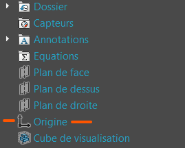
Here we would have to fix a piece, with the correct trihedron ideally (see @sylk's message) then constrain everything to this piece and gradually make disappear the (-) that indicates at least one degree of freedom to the piece (or more!)
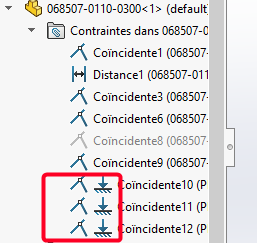
Edit:
Here the 1st piece is fixed (f), the 2nd is totally constrained (no (-) and the 3rd has at least 1 degree of freedom (-):

Edit2:
If the part is totally constrained, but not fixed, the stresses of this part fixing it to an axis or plane are recognized by the following symbol (as hung on the ground):
1 Like
Hello Patrick,
As for the function moved bodies, it can only be used in the context of a part and not in the context of an assembly. So it's not suitable to be used in your case in an assembly.
If you absolutely want to use it, register your assembly as a part.
Open your room and there you will have a multitude of bodies where you can use your function.
PS: moving the bodies and moving the faces are recommended only in specific cases where you don't want to lose a surface reference and otherwise mainly to rework a step. Otherwise it becomes very quickly complicated to resume 3D for you in 6 months or for any other user.
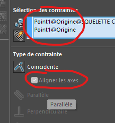
You can also select the origin of your assembly and your part and in a single constraint, constrain your part.
But it implies that your axes and planes are oriented in your part and in your assembly in the same way.
For your information, I'm reading you and when you say " snatch coerce", from experience everything you do snatching will cause you a problem at one time or another. Orientations (example Z at the top) are essential when defining your design in a 3D environment.
One last piece of advice, the so-called positioning constraints (parallelism and perpendicularity) should be avoided (except when there is nothing blocking a condition). You'll see in the end where you've all blocked and that you'll remove these constraints, that your pieces will always be constrained.
And sometimes, they will cause problems of over-stress when SolidWorks accumulates them in the combination of your parts assemblies and their constraints
Good luck
2 Likes
Thank you all for your wise advice and contributions to reorient my youthful flaws (well almost, because I am training on the job now retired ![]() )
)
FRED 78, I tested the coincidence stress and align the axes on a new part in a new assembly taking care to align the original axes ![]()
Now I hope not to create inconsistencies on the use of my assemblies and parts when they are exported as a Step for a CAD! That said, I haven't (yet) had any feedback on inconsistencies!
Thank you again and happy new year and success in your projects.
1 Like