I am contacting you because I very often work on multibody parts to make sheet metal junction ducts, made up of several panels bolted together to facilitate handling and installation.
My current method is as follows: • I create a complete volume body, • I connect the two openings with a smoothing, • I model the flanges in volume, • then I create the folds in volume according to the shape I have in mind, • Finally, I convert my body into several panels.
The problem is that at the time of conversion, I very often: • corners that do not close properly, • small residual edges that prevent conversion, • folds that do not meet neatly, • or even some faces that completely refuse to be converted to sheet metal.
In summary, as soon as the geometry becomes a bit complex, it becomes difficult to get clean panels that fit well together.
So I wanted to know how you proceed for this type of part and if you have any tips, methods or best practices to share to make this work in SolidWorks reliable.
I will rely on a 3D sketch defining the major dimensions. I will use the sheet metal functions to stay in the field of realization. After as said @Silver_Surfer without an example of your problem it is difficult to understand the blocking points
Personally, I will work with " classic " sheet metal parts. I avoid the volume = conversion as much as possible> Sheet metal, it's not always easy to modify the geometry afterwards. And the reliability of the conversion module depends a lot on the version of Solidworks used. Relying on a complete volume body to position the sheets or evaluate the docking is not a bad idea but I do not recommend using it for stresses.
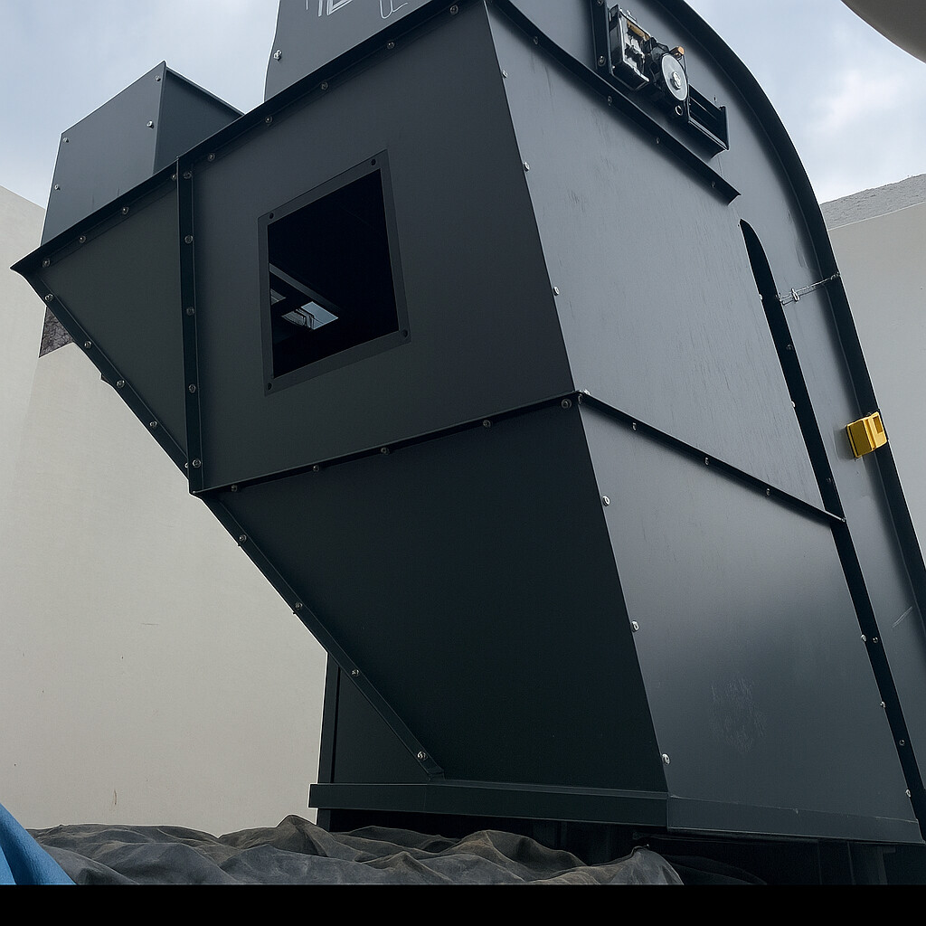
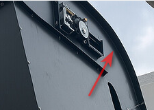
Don't hesitate to make sub-assemblies. Avoid 3D sketching as much as possible with the Sheet Metal module. Use the drilling assistant as much as possible (and the repetitions by functions, especially for bolts.) Don't go into non-unfoldable parts (I'm thinking of the bent sides of the conveyor in the photo. Avoid symmetries of sheet metal components.
Yes, I understand: when the folds are 90° and the chute does not have several angles, it makes sense to separate the pieces; I think this is the best practice. But for pieces like this, how do you go about it?
For your information, in 2025, a simple reconstruction of the model " PRESENTATION PROBLEM. SLDPRT " via a ctr+Q generates a lot of errors. For me, the use of the Boundary function without a pilot curve is bound to create problems (geometry is very poorly mastered with this type of function → the ' flat ' faces may not be so in practice with this function.
On the other hand, I am not necessarily the main user of the Frontier function: I took this part after a colleague. For this particular part, it worked fine.
I don't know if anyone is used to working on pieces like this.
Should we go through a volume body that we then split, then use the Shell function before making a conversion?
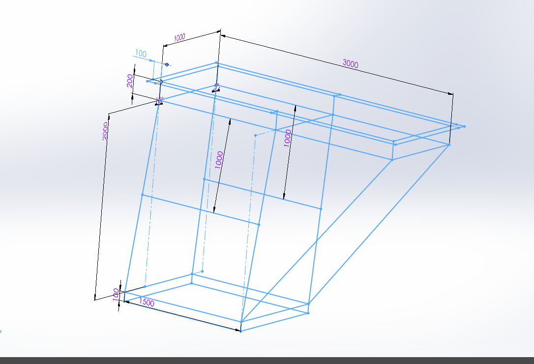
@anthony_bellin Item1.SLDPRT (71.3 KB) Lean on this skeleton, adapt the dimensions or sketches. If you sketch the geometry this way, you should get there or find a solution that will work for you. Rather than feeling our way around.
Think about the manufacture that the angles are as much as possible 90° or more. If the corners are closed, provide sufficient clearance for the screws. In short, it's up to you
When you make pieces of this type it is sometimes complicated to modify when you are in multi-body without breaking everything
The hull function is not very realistic for manufacturing, everything will have to be anticipated. Provide reinforcement and flanges at the junction complicate bring back bolted simpler I think
Yes, bolted clamps would have been simpler... I had already relied on this type of design before, but in a case where you impose fully folded flaps like the ones I had to make, I found that the management of folds/flaps and good connections was more complicated by going through a 3D sketch.
The flap fold you make them directly in your room in 3D, this skeleton is there to size and orient your sketches in your parts, like in the example I sent you yesterday. The idea is to control via this part (skeleton) in an assembly of parts in external reference, you rely on your skeleton in short. This allows you not to look for external references everywhere, and to create X useless and duplicate plans, it structures your design.
The details, folds, chewing, chamfering, you do it on your 3D without necessarily going through your skeleton.
In our case, one of the designers made a part = Assembly containing, a skeleton and a part or several systematically. Each piece is independent. We prefer this technique to integrating a room into a room (which also works, well... almost at home )
The method ! It's very simple you do it every day in 3D, but here we structure the work by concentrating your external references on a single part. This simplifies the search when there are errors or need for modification.
Create a part (internal or external, it doesn't matter) in your assembly
Edit the part in context
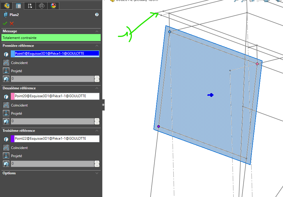
Create a plan by tapping on the skeleton (1) skeleton
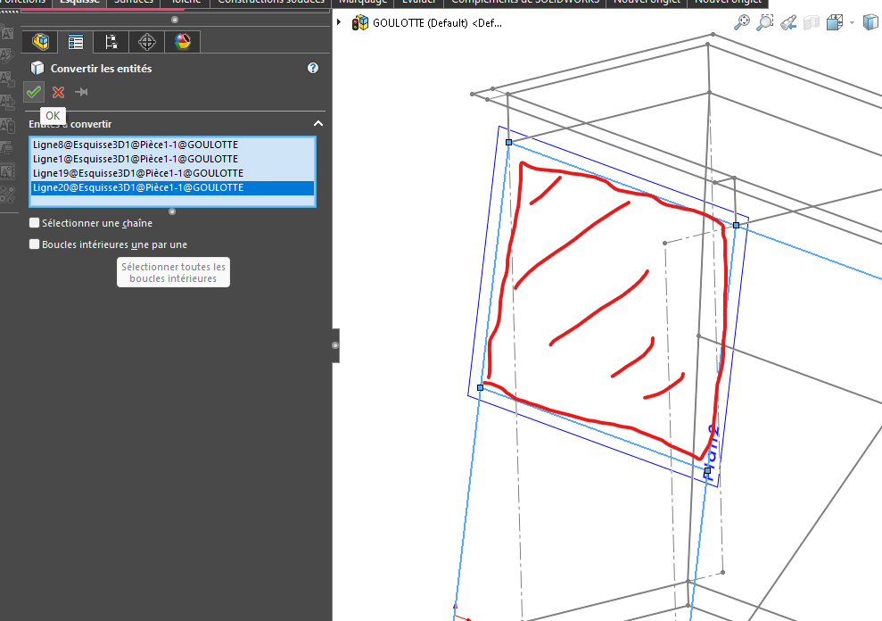
Create a sketch on this plane and import the sketch entities onto the skeleton (external reference)
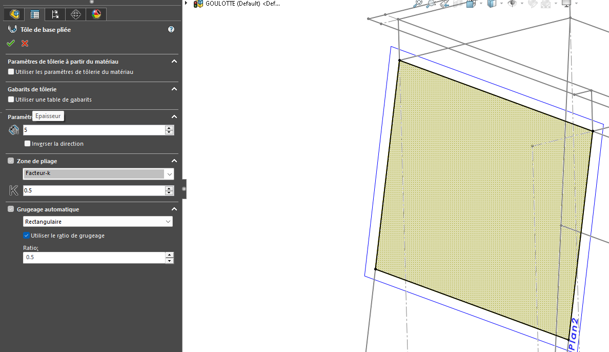
Create the sheet metal on your sketch
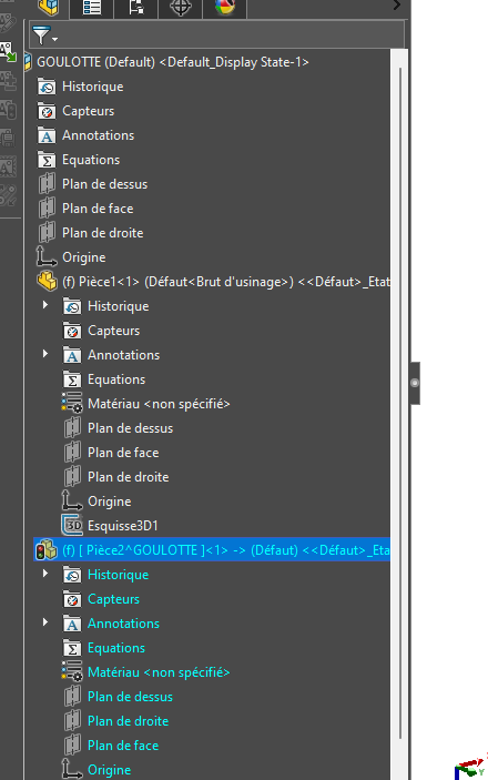
For some parts with several bodies, you can either create a sub-assembly or a multi-body GOULOTTES.zip (644.3 KB) I gave you an example. (Forgive me for the design, I did it quickly
To go in the direction of the proposal of @FRED78 ...
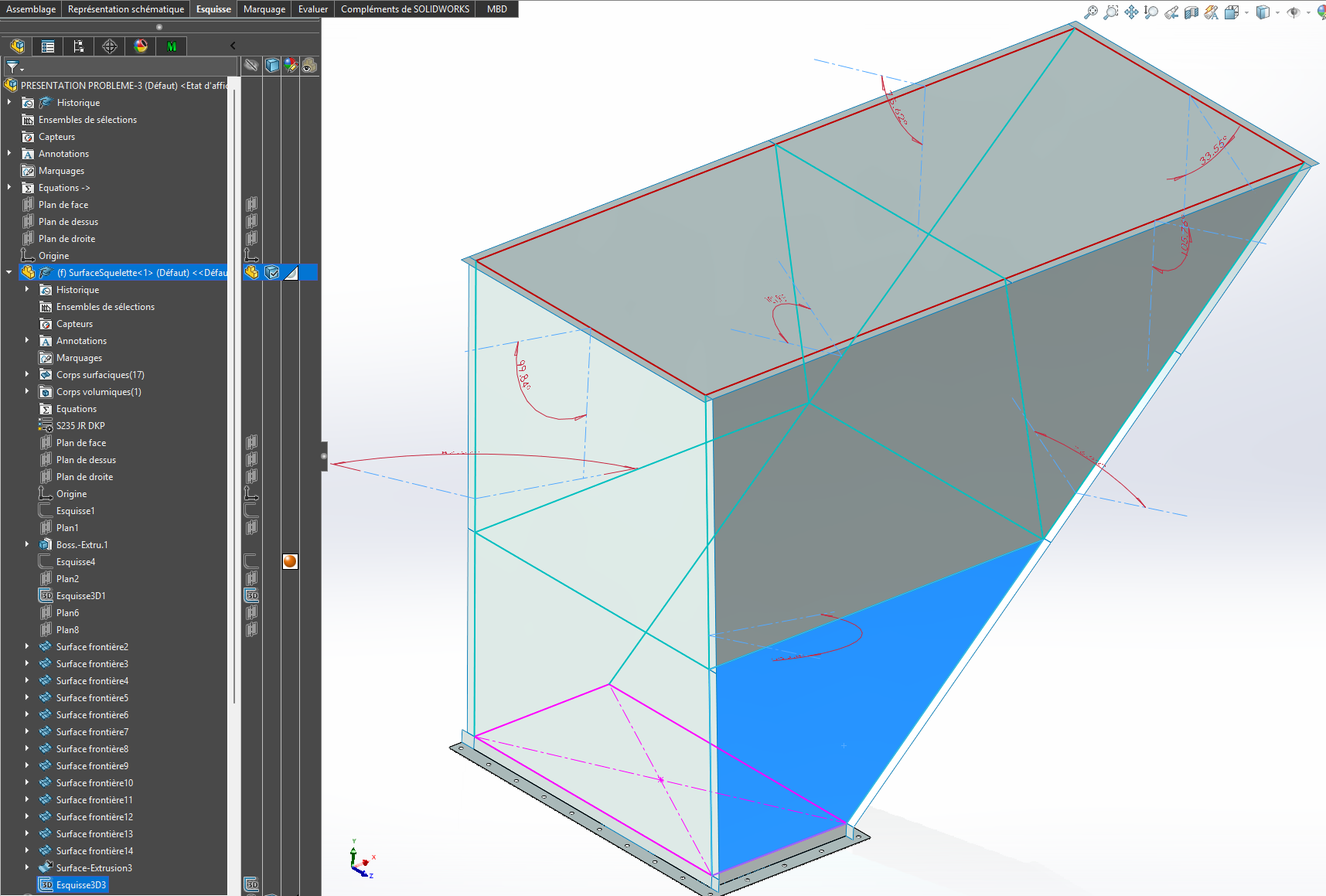
In the skeleton part, whose 2D and 3D sketches define the overall geometry, I would add all the flat surfaces that make up both the inside of the chute, as well as the support faces of the flaps between sheet metal elements. In a second step, the parts are created in an assembly, exclusively with the sheet metal functions of Solidworks.
Each piece is based on a copy of the corresponding surface of the skeleton, for example the trapezoidal face in the image above. Interest: no sketches to generate in the rooms. All that remains is to create the flaps, with several " problems ":
the angles of the flaps: if they do not have simple and known values (30, 45, 90 degrees, etc.), as is the case on the chute proposed as an example, it is possible to dimension the angles between faces, still in the skeleton, and then to use them for the definition of the flaps;
The same approach applies to flap width, which can be defined by a global variable (or several);
need to resketch some of the flaps to manage possible collisions in the corners.
These problems are compensated by the possibility of modifying the geometry of the chute later (within reasonable limits).
Quote = In the skeleton part whose 2D and 3D sketches define the overall geometry, I would add the set of flat surfaces that make up both the inside of the chute, as well as the support faces of the flaps between sheet metal elements. In a second step, the parts are created in an assembly, exclusively with the sheet metal functions of SolidWorks
All the details are good to put in as long as it suits you to manage your ensemble. And if you want to go further in this method. You can create subskeletons (2electricity, piping), always be careful when going down so as not to create a loop (Parent / child). And in this case you can use the method of inserting a coin into a coin. The idea is that when you make a modification on one of the subskeletons, you don't impact the others. So your SW updates are shorter.
For commercial elements, I create an assembly, I insert a skeleton and I constrain my camera on it that allows me to insert and fix it origin to origin. On the same principle as everything else, it is not one Object that moves in relation to another, it is the part that moves in its space through a common origin driven by the skeleton, because it is constrained by it.
With this method of fixing your origin to origin assemblies you remove all your constraints on your parts. You'll have some for the screws only, it's already more than enough to slow down your PC.