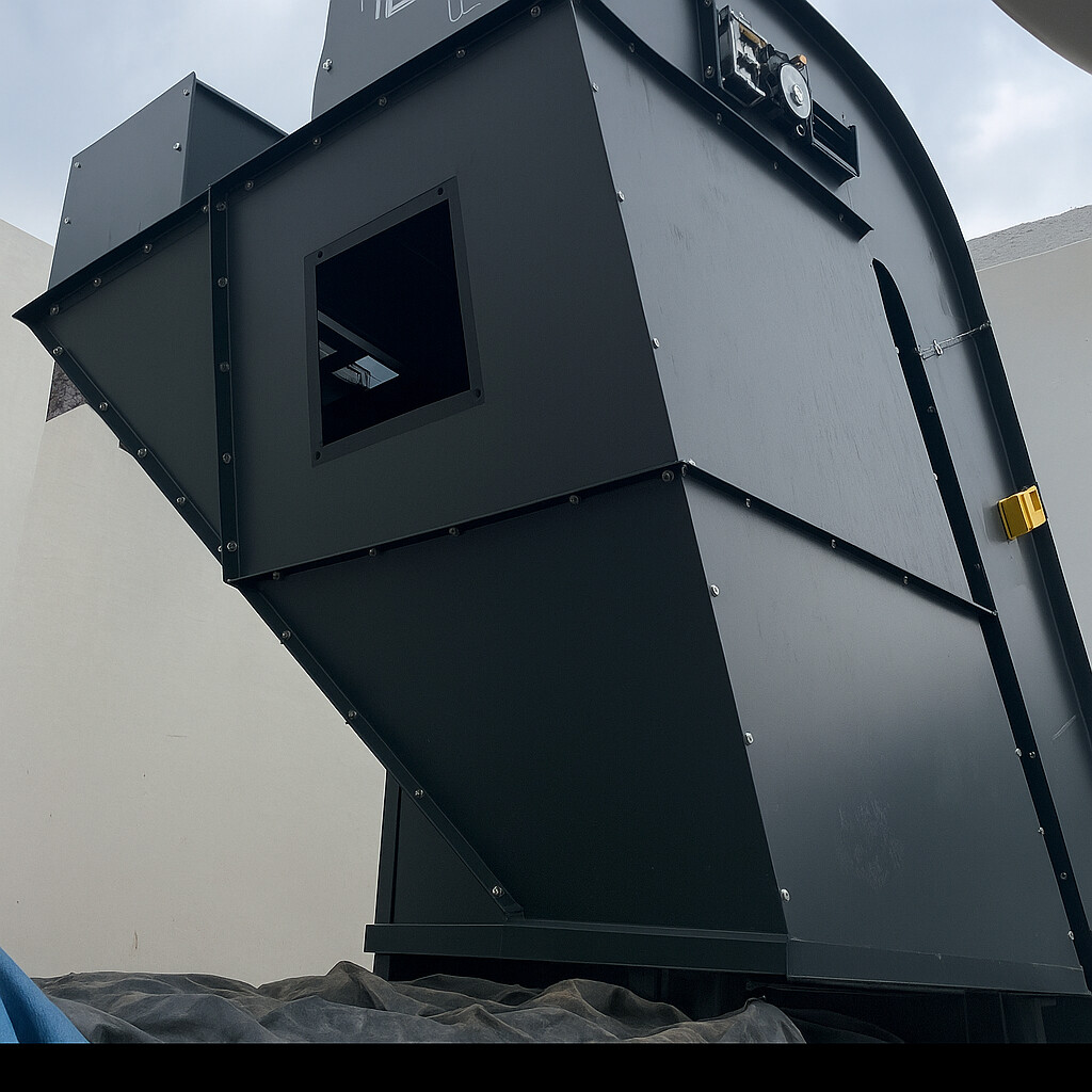
I am contacting you because I very often work on multibody parts to make sheet metal junction ducts, made up of several panels bolted together to facilitate handling and installation.
My current method is as follows: • I create a complete volume body, • I connect the two openings with a smoothing, • I model the flanges in volume, • then I create the folds in volume according to the shape I have in mind, • Finally, I convert my body into several panels.
The problem is that at the time of conversion, I very often: • corners that do not close properly, • small residual edges that prevent conversion, • folds that do not meet neatly, • or even some faces that completely refuse to be converted to sheet metal.
In summary, as soon as the geometry becomes a bit complex, it becomes difficult to get clean panels that fit well together.
So I wanted to know how you proceed for this type of part and if you have any tips, methods or best practices to share to make this work in SolidWorks reliable.
I will rely on a 3D sketch defining the major dimensions. I will use the sheet metal functions to stay in the field of realization. After as said @Silver_Surfer without an example of your problem it is difficult to understand the blocking points
Personally, I will work with " classic " sheet metal parts. I avoid the volume = conversion as much as possible> Sheet metal, it's not always easy to modify the geometry afterwards. And the reliability of the conversion module depends a lot on the version of Solidworks used. Relying on a complete volume body to position the sheets or evaluate the docking is not a bad idea but I do not recommend using it for stresses.
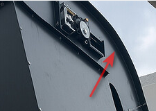
Don't hesitate to make sub-assemblies. Avoid 3D sketching as much as possible with the Sheet Metal module. Use the drilling assistant as much as possible (and the repetitions by functions, especially for bolts.) Don't go into non-unfoldable parts (I'm thinking of the bent sides of the conveyor in the photo. Avoid symmetries of sheet metal components.
Yes, I understand: when the folds are 90° and the chute does not have several angles, it makes sense to separate the pieces; I think this is the best practice. But for pieces like this, how do you go about it?
For your information, in 2025, a simple reconstruction of the model " PRESENTATION PROBLEM. SLDPRT " via a ctr+Q generates a lot of errors. For me, the use of the Boundary function without a pilot curve is bound to create problems (geometry is very poorly mastered with this type of function → the ' flat ' faces may not be so in practice with this function.