Hello
I am currently trying to determine if my tie rod under tension does not exceed the elastic limit.
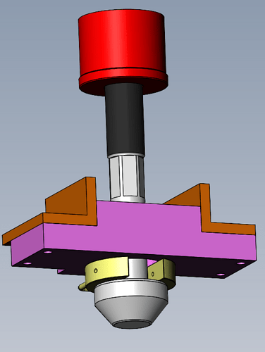
Schematically, a hydraulic nut is supported through its washer on a fixed part (all in red, excluded from the analysis). The tie rod in grey through the yellow clasp comes to press the chair in pink on a fixed part in orange (non-deformable, not recalculated).
The materials are S355JR for the pink chair, 42CrMo4 for the grey tie rod and the yellow clad.
I am subject to 2 problems:
The first is that I can't determine an elastic limit to the matter itself. On Total materia I get a range of RP0.2 from 390 to 650 MPa, while at Aubert & Duval I get 1500 MPa in forged...
What to take as a reference?
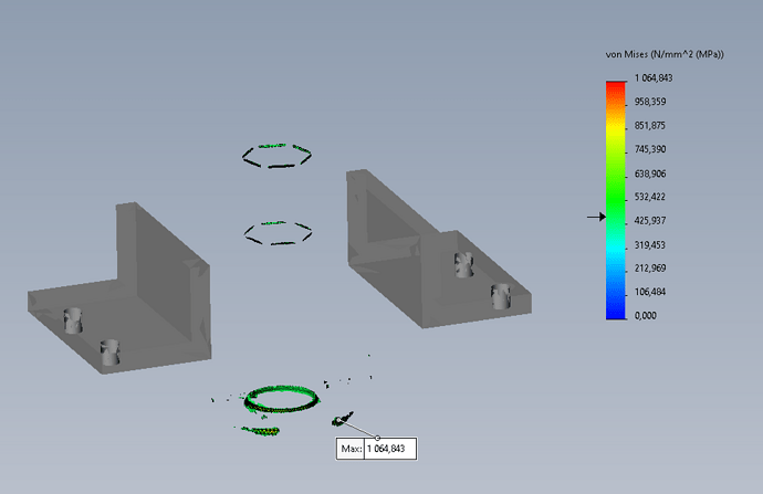
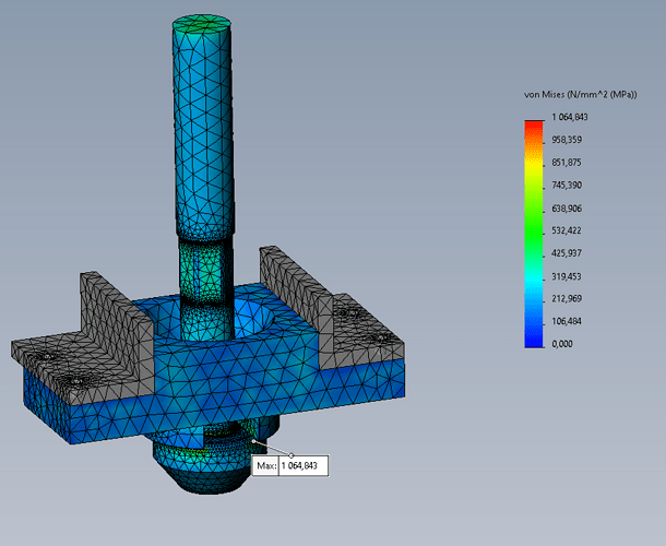
The second question I ask myself is that the maximum stress located at the level of the clam is 1064 MPa.
The more I refine the mesh, the higher the value goes. How far should I refine it in this case?
To be more complete, I take up an NDC already made where the person who wrote it said that the gauge went to 2046 MPa, without specifying where or how...
If you need more details...
I post the template
Assemblage1.zip (46.8 MB)
Thank you
Hello @clement.merlin
It would be better if you joined us at the ASM by attaching the results of the analysis, all by means of a zipped pack and go. Indeed, it is only by looking at your parameters that we can give you a humble opinion.
However, some things like the slight deformation of the pink piece while the gray brackets don't show any deformation catch my attention
Confirm to me that I understood that what interests you is the gray part (the black one being the rod of the cylinder).
Can you confirm the names of the different parts (e.g. CLAME ???)
Kind regards
1 Like
Hello
The black and the grey are one and the same piece. The black part is just a thread representation.
The 2 brackets that do not deform are put "non-deformable" in the software.
The vocabulary itself comes from the customer, I don't contradict ^^
Hello
I delayed my answer a little because of the beach at the sea.
As you have a version prior to mine, I cannot send you the result of my simulation.
That is why I have sent you the report in PDF form.
My comments!
1°) from the moment that the orange brackets are deemed to be non-deformable, they should not have been included in the analysis. You will notice that in the analysis they deform very slightly without this having any impact on the result.
2°) for the solver I favored automatic rather than a particular solver
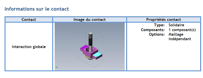
3° ) for the contacts I used solidarity
4°) given that the brackets are reputed to be non-deformable, they could have been excluded from the analysis. In this case it was enough to put fixed displacements on the support surfaces of the orange piece on the rose.
5°) in the mesh parameters use rather curvature-based mesh (rather than connected mesh in your case.
For the mesh, it does not have to be very fine since what interests is the " tie rod assembly segment "!
6° you have not defined a criterion for ruin before the results are released.
In your results you should add the safety coeff. This reveals that you have zones at 2.18, 2.42, and 2.87 on the tie rod which seems a bit low to me (but I don't know the conditions of use (shocks, vibrations; etc...)
Also in the results I suggest you display the " design dissection" which will show you why the Von Mises results are looking this way.
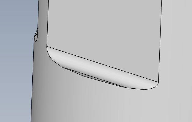
From this point of view, the milling of the flats used for wrench tightening have right angles. If you take a strawberry with a hearty radius, it's going to solidify those parts a little bit weak.
Kind regards
Assembly1-Static 1-1.pdf (482.4 KB)
1 Like
Hello
I would like to return a few more questions following your points:
- ok it's logical I should have thought about it
- Why in auto and not preselect a solver? (I followed the chief's advice but didn't understand why...)
- OK
- OK
- Why not connected to the curvature? I understood that it helped when you simulated an assembly for the continuity of the meshes between the parts...
I also thought that a finer mesh helped to locate stress concentrations, especially at the tie rod
- We're going for VonMises, but I don't have the customer's feedback yet for the Re max of the 42CrMo4 (the model is TQC of course).
If you talk about these right angles of the flats
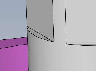
My boss advised me to remove the leaves I had put for the simulation, in order to avoid micro surfaces with a delicate mesh.
Moreover in your NDC, I see that Jacobian stitches are at 16pts, where my boss advised me to put it " in knots ". Could you explain why you chose this?
Still in your NDC page 8 I see a max at 981 MPa but the graph stops at max at 337. Did you discriminate against any part of the model? If so, how and why? (looking at the volume of geometric elements this would represent less than 0.01% of the model, which if I remember the formation correctly can be considered " negligible ").
By redoing the calculation on my side I find myself with a volume of 23% above 337 MPa... I don't understand where this can come from.
Assembly1-Static 1-3.pdf (634.3 KB)
As an aside, during my previous simulations, this info of the ratio "volume (elements/geometric) = X% / X% was not visible, is there an option that I would not have checked?
I'm just trying to understand what's best, not to shoot my boss or whoever we get along 
Thank you
Don't tell him but I don't agree with your boss 
What for?
All mechanics know that right angles are so many beginnings of breakage! hence the shelving.
In the simulation of your asm, which is not complicated, I used a rather coarse mesh without it moving anyone
In the case of the reasonable use of small rays, there are several ways to proceed
a) Mesh the model with the " automatic transition" option. This automatically applies the mesh controls to small details, entities, holes, and fillets.
This obviously depends on the curvature of the geometry. Refining the mesh allows for accurate stress results.
In two words:
It should be kept in mind that any resolution obtained using a PEF analysis depends on how the model was meshed.
It is also necessary to understand the refining process (which responds to the chef's objection to the corner racks.
Refining makes it possible to better control singular constraints.
I suggest that you read up on the two adaptive methods " H " and " P " and compare them to the standard type of resolution.
In your report, the design dissection is not good, you have to put the cursor further away to really see the most stressed areas. This will be more consistent with the safety coeff which I find a little low given the traction exerted. (but hey, I'm not the Chef 
Kind regards
PS: I don't know what I mean (the template is TQC obviously). But if such a simple rod becomes a confidential defense then everything I do becomes touchy 
So I say that we define a part not to please the simulation (elimination of rays) but according to the greatest solidity in relation to the use that will be made of the part 
Thank you,
I had just found this which talks about the H and P methods
What is Convergence in Finite Element Analysis? SimScale
I'm going to take a closer look at all of this.
A big thank you in any case
TQC for us: As Built = traditional test method aimed at manufacturing and mounting on the machine AVANt to pass the parts to the calculation, and complain because it breaks 
Hello
A few remarks:
- it seems that the design you calculate is not good given your comments about TQC and breakage. It would be good to specify where
- There are always concentrations of stress in the radii, the smaller the radius (or even almost zero) the higher it is. Meshing with a size much larger than the real radii greatly minimizes the constraints in the results (we quickly have a coeff of 2 to 5 between an ultra-coarse mesh and a fine mesh)
- Removing the rays where there is no problem allows you to go faster in meshing / calculation (but during our days it will be femto second difference). This is understandable, especially if the mesh modification is not in the critical zone (I think it is and that would explain why your old boss told you to remove the spokes (old because at the time EF calculations took days and simplifying the model saved hours))
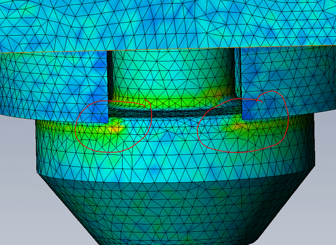
If you have the problem of breakage at the level of the small radius here
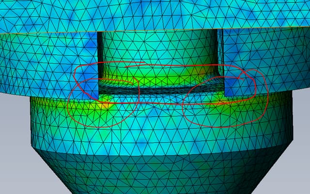
, you had indeed better have a minimum of 3 or 4 elements on the length of your radius (quite small mesh size at the time) if you want to have an idea of the real constraint at this point
Except on concrete, we usually don't care about compression (your two circles on the image above), I doubt that this is the area of the rupture start.
42CrMo4 is a material that must undergo heat treatment. Depending on the process and the quality of the treatment, the size of the part... the Rp0.2 and the Rm will be different and will also be different depending on whether you are in the heart of the room or outside it.
You can make a hardness next to the broken area, there are equivalents of hardness ↔ Rm
The permissible stresses of the part also depend on the range of fab: machining then heat treatment or heat treatment on the stock then machining.
If you have machined a previously treated stock, it should not be surprising that the material is not very resistant at the level of the diameter I have surrounded (it is the heart of the part so a place less heat treated than the outside of it.
Another question: does the part work in fatigue? If so, what type of fatigue? Depending on the material, you must quickly divide the permissible stresses by 2 or 3 if you want to reach hundreds of thousands of cycles.
The visual analysis of the broken part generally makes it possible to know if there was fatigue or if there was a clean breakage without prior fatigue.
Given the problem, the analysis must be carried out by managing the contacts at critical points in order to allow the parts to peel off and flex realistically. Have contacts like these:
will not allow you to obtain correct analysis results (all parts are welded together → much more rigid model than in reality → stresses much lower than in reality)
PS: if the pb is in the area I have circled, increasing the radius to the maximum (even if it means adding a radius/chamfer on the C-piece) is probably a good idea if you want a more resistant design (without changing other parameters such as the fab range or the materials)
2 Likes
Hello
For heists, it's a bit of an ironic joke (but overall it's in the spirit).
I note for the mesh sizes of the rays, I'm going to play around with it a little bit to see the different results that I get.
My boss is not that old XD but I note the remark.
Regarding compression, however, you can't exceed the elastic limit though? I have a hard time following on this part...
For the treatment, I have a diameter of 150 on the stock, and a machined diameter of 66mm... Indeed, I have researched the subject, I will have the pieces redone following a more square treatment protocol.
The part is not supposed to work in fatigue. I'm already starting with a coef 2
For the contacts I test with other options.
Thank you very much
