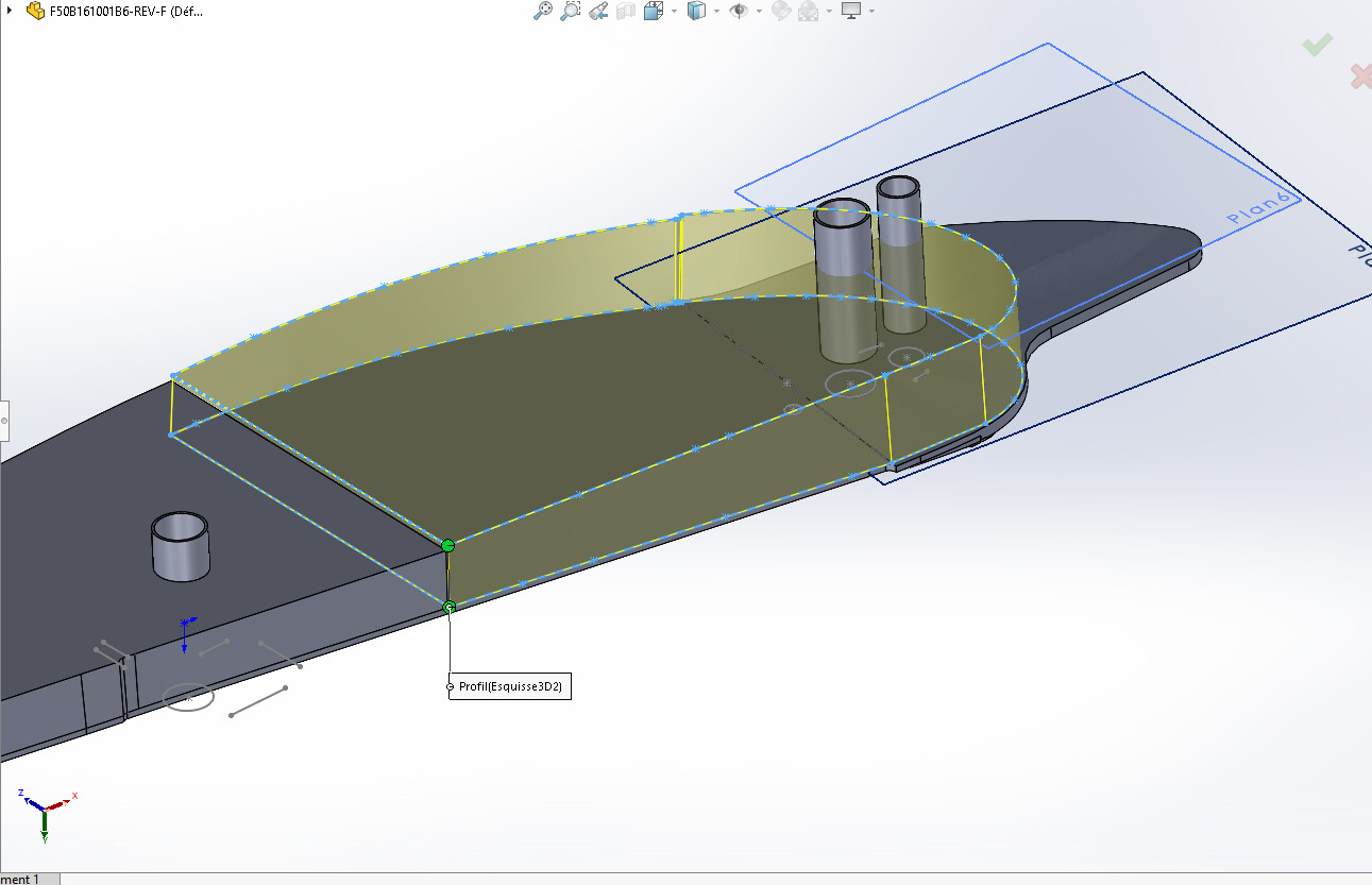
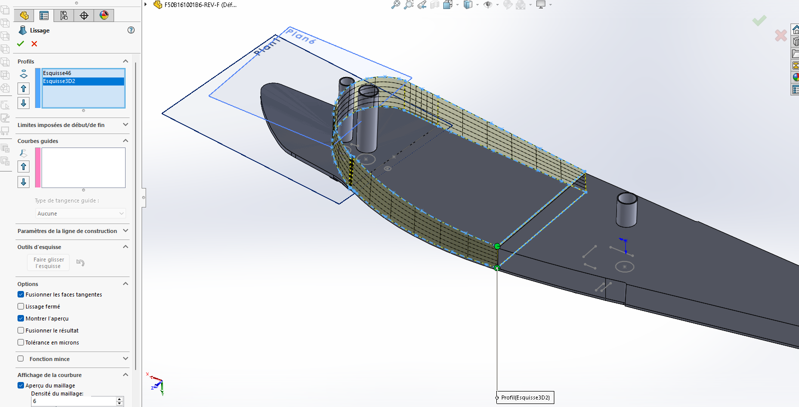
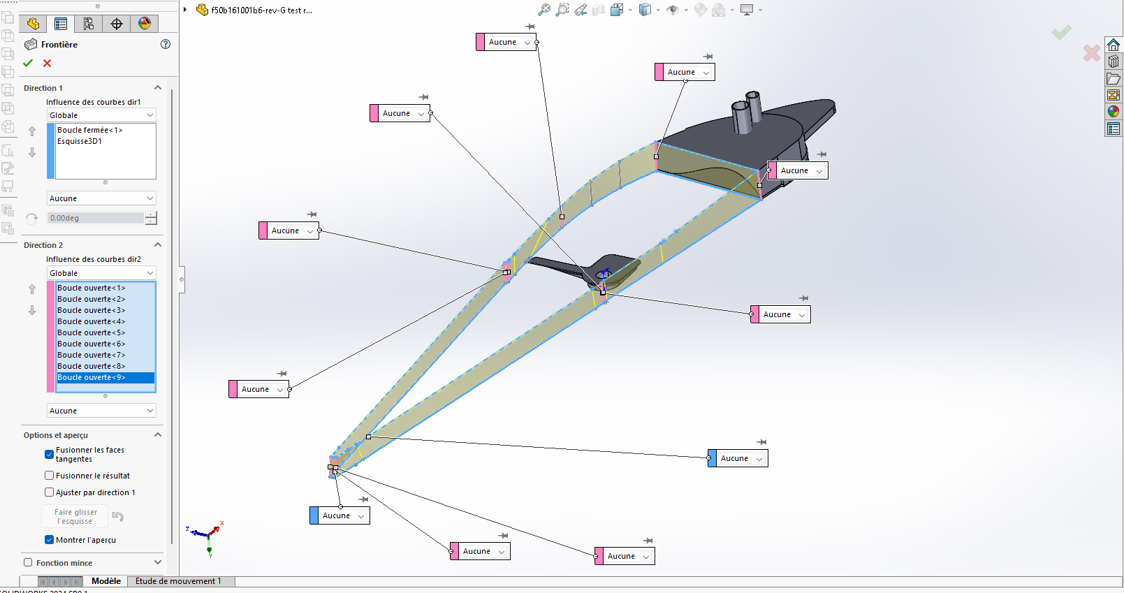
Hello. I am having a problem that I can't seem to solve on SolidWorks. I'm detailing the problem: I'm in the process of redesigning a really crooked part (aeronautics) I have the part in real life and I have a KEYENCE camera with probe. in short I have a problem on a smoothing that I would like to do. impossible to solve the following error, either it's "the smoothing operation was not completed" or it's the geometry has a zero thickness. I ask to show me the preview and apparently no problem but it fails every time. As for the null geometry I have already shifted one of the faces because I thought it was the joint that was the problem but its nothing solved
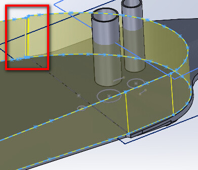
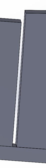
Hello; Also remember to specify the Solidworks version used. … Without getting too far ahead of myself, the problem seems to be on the basic sketch (circled in red).
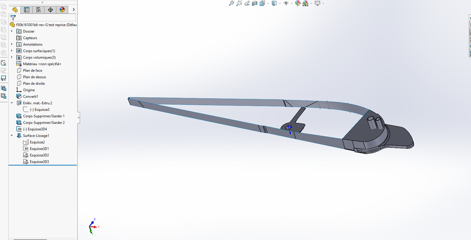
Is there a reason to make an additional body, rather than extending the existing body and removing matter from it (seems simpler to me). I can't help you any more (Solidworks 2022 for me.)
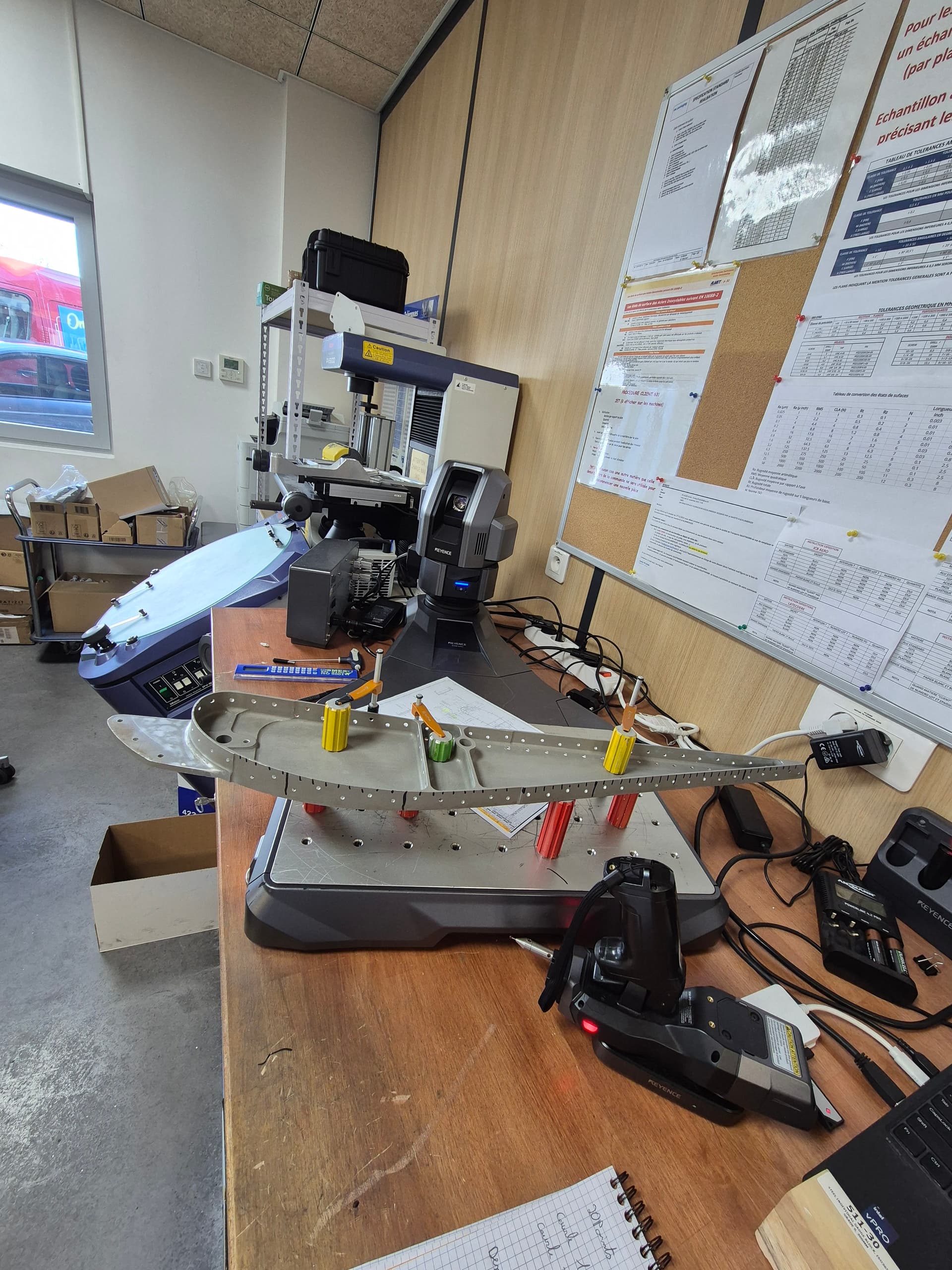
the reason is that the part is mounted on a Falcon F50 and it has reproduced identically. The piece is twisted and curved. I first draw the bottom part and check it directly on Tridi by feeling the real part. like its I validate the shape of the bottom before tackling the whole. The part dates from 1984 (it is a moving part of an aero brake) it must be reproduced at more or less 0.2 mm to machine it. I work step by step because where I work I am also a quality controller and MIG welder. In short, it's another subject ^^ the cylinders through allow me to locate the DXF blocks that I create with the Keyence camera. This allows me to reposition myself at each stage.
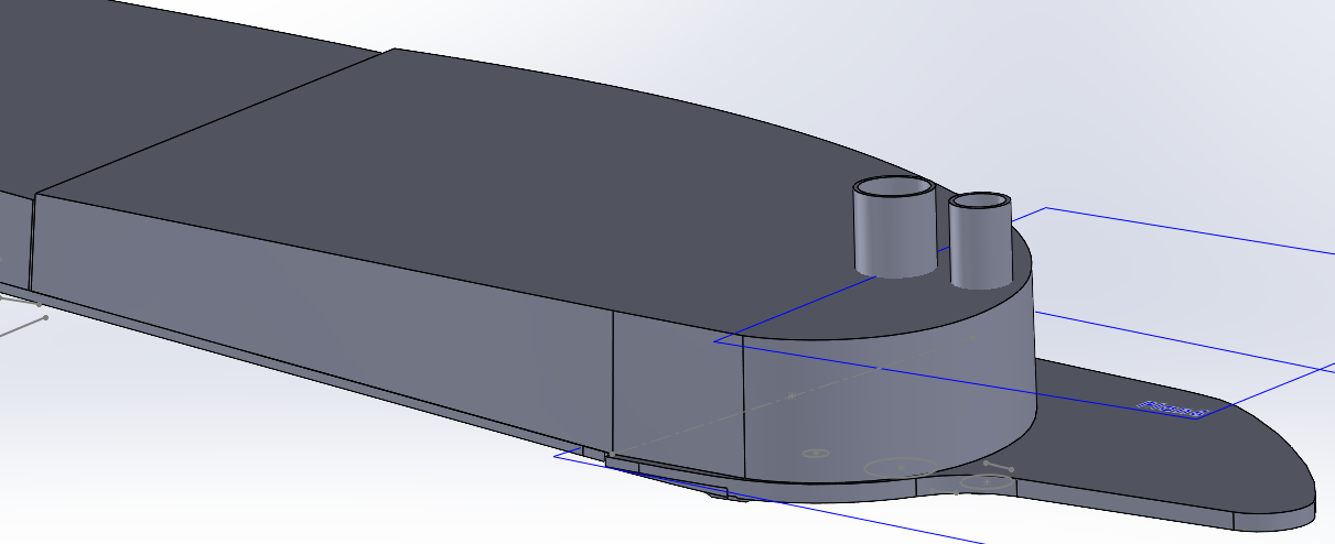
EDIT: EUREKA ! It worked strangely the overview did not stick to reality either base border but it works. I do have my play. Thank you very much for the time.
Great, so I looked a little further after moving forward on the project I checked my complete curve at the tridi I am within the tolerance of 2/10 so I wanted to make the room cleaner but I find myself stuck again. I took all the points from the first part and I try to redo either a border base or a smooth base and rebelotte. impossible. The same message comes back. "Impossible to create a 3D tip face" I don't understand.
I would then like to rework the rear part cleanly but if I can't already do the front part it's not a win. Here is the 2022 version of the coin f50b161001b6 v 2022.SLDPRT (1.6 MB)
And for those who are wondering, here is a picture of the play posing in front of the camera. and unfortunately I don't have a scanner there is still a little work in it but by making pockets it should be fine.
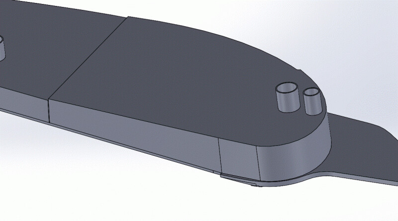
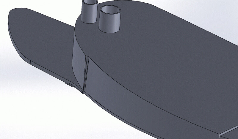
I also manage to do the outline, that said it's mostly the upper shapes On the first part on the left of the photo and limiting up to the lateral hook which is a problem, I get there. I create two surfaces above and below, and I extrude both surfaces and I get volume. With the surface tools. You have to go by section I suppose it is not possible to simplify the forms.