Macro solidworks to generate welded constructions

Hi all

I'm looking for a piece of code that will allow me to generate a welded construction.
I have tubular structures to create that are very similar to each other.

Tubular structures are always an assembly of tubes in the same plane, this structure is always rectangular and has a number of horizontal and vertical tubes spaced less than 500mm apart.

I would like to have a code for a working base that generates the basic sketch and applies the tubes on this sketch.

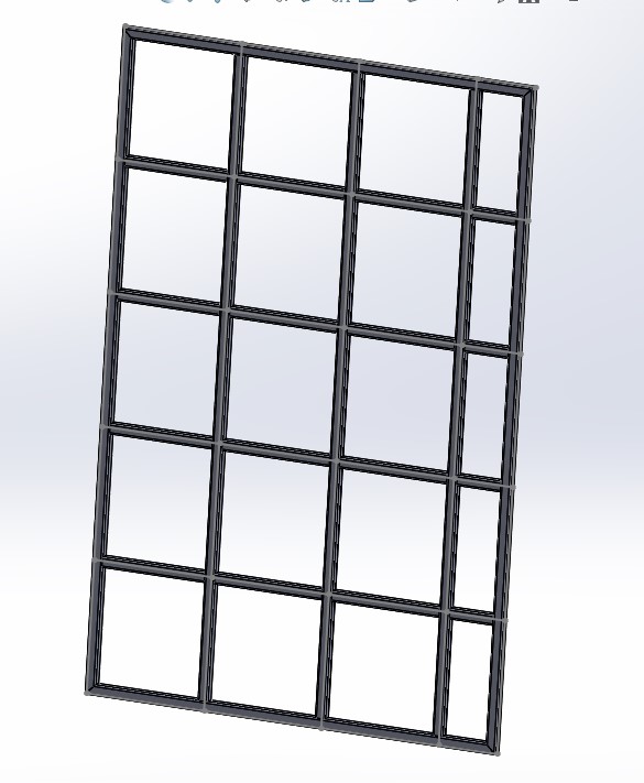
Here's an example of what I want to create per macro:
Screenshot_55

I think a base with a frame is a cross in the middle should be enough for me to automate the rest, but I'm taking anything you might come up with.
Because I have never created a macro-welded construction.

I'm thinking of going through a UserForm to enter my basic data, and then generate the structure.

I hope I've been clear enough, otherwise don't hesitate to ask me.

I got this code that allows you to create a welded construction thanks to an existing sketch.

The problem is that when I launch the code with a sketch that has 6 segments, there are only 5 that go into welded construction.
This seems obvious because " i=1 ".
However when I put i=0, the code no longer works, there is no more soldered construction that is created.

Code with i=1:

Dim swApp As SldWorks.SldWorks
Dim Part As ModelDoc2
Dim boolstatus As Boolean
Dim FeatMgr As FeatureManager
Dim SelMgr As SelectionMgr
Dim mySketch As SldWorks.Sketch
Dim swWeldFeat As SldWorks.Feature
Dim swWeldFeatData As SldWorks.StructuralMemberFeatureData
Dim skSegCount As Long
Dim vSkSegments As Variant
Dim skSegment As SldWorks.SketchSegment
Dim i As Integer

Option Explicit

Public Sub Main()

    Set swApp = Application.SldWorks
    Set Part = swApp.ActiveDoc
    Set FeatMgr = Part.FeatureManager
    Set SelMgr = Part.SelectionManager

    Dim myFeature2 As Object
    Set myFeature2 = Part.FeatureByName("NdM 3D")
    Set mySketch = myFeature2.GetSpecificFeature2()
    vSkSegments = mySketch.GetSketchSegments()
    skSegCount = UBound(vSkSegments)
    Debug.Print "    nombre de segments dans l'esquisse = " & skSegCount
    
    Dim myFeature As Object
    Set myFeature = Part.FeatureManager.InsertWeldmentFeature()
    Dim GroupArray() As Object
    ReDim GroupArray(0 To 100) As Object
    
    For i = 1 To UBound(vSkSegments)
        Dim Group As StructuralMemberGroup
        Set Group = FeatMgr.CreateStructuralMemberGroup
        Dim Segments(0) As Object
        boolstatus = Part.Extension.SelectByID2("Line" & i & "@NdM 3D", "EXTSKETCHSEGMENT", 0, 0, 0, False, 0, Nothing, 0)
        Set Segments(0) = SelMgr.GetSelectedObject6(1, 0)
        Debug.Print "  Sketch = " & vSkSegments(i-1).GetName
        Debug.Print "  Sketch = " & vSkSegments(i-1).GetLength
        Group.Segments = (Segments)
        Set GroupArray(i-1) = Group
    Next i

    Set myFeature = Part.FeatureManager.InsertStructuralWeldment4("C:\Program Files\SOLIDWORKS Corp 2022\SOLIDWORKS\lang\french\weldment profiles\ISO\Tube (square)\40 x 40 x 3.2.sldlfp", 1, False, (GroupArray))
    Part.ClearSelection2 True

End Sub

Code with i=0:

Dim swApp As SldWorks.SldWorks
Dim Part As ModelDoc2
Dim boolstatus As Boolean
Dim FeatMgr As FeatureManager
Dim SelMgr As SelectionMgr
Dim mySketch As SldWorks.Sketch
Dim swWeldFeat As SldWorks.Feature
Dim swWeldFeatData As SldWorks.StructuralMemberFeatureData
Dim skSegCount As Long
Dim vSkSegments As Variant
Dim skSegment As SldWorks.SketchSegment
Dim i As Integer

Option Explicit

Public Sub Main()

    Set swApp = Application.SldWorks
    Set Part = swApp.ActiveDoc
    Set FeatMgr = Part.FeatureManager
    Set SelMgr = Part.SelectionManager

    Dim myFeature2 As Object
    Set myFeature2 = Part.FeatureByName("NdM 3D")
    Set mySketch = myFeature2.GetSpecificFeature2()
    vSkSegments = mySketch.GetSketchSegments()
    skSegCount = UBound(vSkSegments)
    Debug.Print "    nombre de segments dans l'esquisse = " & skSegCount
    
    Dim myFeature As Object
    Set myFeature = Part.FeatureManager.InsertWeldmentFeature()
    Dim GroupArray() As Object
    ReDim GroupArray(0 To 100) As Object
    
    For i = 0 To UBound(vSkSegments)
        Dim Group As StructuralMemberGroup
        Set Group = FeatMgr.CreateStructuralMemberGroup
        Dim Segments(0) As Object
        boolstatus = Part.Extension.SelectByID2("Line" & i & "@NdM 3D", "EXTSKETCHSEGMENT", 0, 0, 0, False, 0, Nothing, 0)
        Set Segments(0) = SelMgr.GetSelectedObject6(1, 0)
        Debug.Print "  Sketch = " & vSkSegments(i).GetName
        Debug.Print "  Sketch = " & vSkSegments(i).GetLength
        Group.Segments = (Segments)
        Set GroupArray(i) = Group
    Next i

    Set myFeature = Part.FeatureManager.InsertStructuralWeldment4("C:\Program Files\SOLIDWORKS Corp 2022\SOLIDWORKS\lang\french\weldment profiles\ISO\Tube (square)\40 x 40 x 3.2.sldlfp", 1, False, (GroupArray))
    Part.ClearSelection2 True

End Sub

Here is the file used for testing:
3D Speaker.SLDPRT (42.5 KB)

For the code problem above I found a solution, segment name problem:

Dim swApp As SldWorks.SldWorks
Dim Part As ModelDoc2
Dim boolstatus As Boolean
Dim FeatMgr As FeatureManager
Dim SelMgr As SelectionMgr
Dim mySketch As SldWorks.Sketch
Dim swWeldFeat As SldWorks.Feature
Dim swWeldFeatData As SldWorks.StructuralMemberFeatureData
Dim skSegCount As Long
Dim vSkSegments As Variant
Dim skSegment As SldWorks.SketchSegment
Dim i As Integer

Option Explicit

Public Sub Main()

    Set swApp = Application.SldWorks
    Set Part = swApp.ActiveDoc
    Set FeatMgr = Part.FeatureManager
    Set SelMgr = Part.SelectionManager

    Dim myFeature2 As Object
    Set myFeature2 = Part.FeatureByName("NdM 3D")
    Set mySketch = myFeature2.GetSpecificFeature2()
    vSkSegments = mySketch.GetSketchSegments()
    skSegCount = UBound(vSkSegments)
    Debug.Print "    nombre de segments dans l'esquisse = " & skSegCount
    
    Dim myFeature As Object
    Set myFeature = Part.FeatureManager.InsertWeldmentFeature()
    Dim GroupArray() As Object
    ReDim GroupArray(0 To 100) As Object
    
    For i = 0 To UBound(vSkSegments)
        Dim Group As StructuralMemberGroup
        Set Group = FeatMgr.CreateStructuralMemberGroup
        Dim Segments(0) As Object
        boolstatus = Part.Extension.SelectByID2(vSkSegments(i).GetName & "@NdM 3D", "EXTSKETCHSEGMENT", 0, 0, 0, False, 0, Nothing, 0)
        Set Segments(0) = SelMgr.GetSelectedObject6(1, 0)
        Debug.Print "  Sketch = " & vSkSegments(i ).GetName
        Debug.Print "  Sketch = " & vSkSegments(i).GetLength
        Group.Segments = (Segments)
        Set GroupArray(i) = Group
        Stop
    Next i
Debug.Print "  Nb in group = " & UBound(GroupArray)
    Set myFeature = Part.FeatureManager.InsertStructuralWeldment4("C:\Program Files\SOLIDWORKS Corp 2022\SOLIDWORKS\lang\french\weldment profiles\ISO\Tube (square)\40 x 40 x 3.2.sldlfp", 1, False, (GroupArray))
    Part.ClearSelection2 True

End Sub

I started at the end, now I have to figure out how to create a sketch by VBA!!

Without talking about code, have you tested with repetitions of fields + small equations?

1 Like

Hello

Don't underestimate the usefulness of macro recording.

Here's a macro I recorded that answers this request:

Dim swApp As Object

Dim Part As Object
Dim boolstatus As Boolean
Dim longstatus As Long, longwarnings As Long

Sub main()

Set swApp = Application.SldWorks

Set Part = swApp.ActiveDoc
boolstatus = Part.Extension.SelectByID2("Plan de dessus", "PLANE", 0, 0, 0, False, 0, Nothing, 0)
Part.SketchManager.InsertSketch True
Part.ClearSelection2 True
boolstatus = Part.Extension.SetUserPreferenceToggle(swUserPreferenceToggle_e.swSketchAddConstToRectEntity, swUserPreferenceOption_e.swDetailingNoOptionSpecified, True)
boolstatus = Part.Extension.SetUserPreferenceToggle(swUserPreferenceToggle_e.swSketchAddConstLineDiagonalType, swUserPreferenceOption_e.swDetailingNoOptionSpecified, True)
Dim vSkLines As Variant
vSkLines = Part.SketchManager.CreateCenterRectangle(0, 0, 0, 0.222, 0.1665, 0)

' Named View
Part.ShowNamedView2 "*Isométrique", 7
Part.ViewZoomtofit2
Part.ClearSelection2 True
Dim skSegment As Object
Set skSegment = Part.SketchManager.CreateLine(-0#, -0.1665, 0#, 0#, 0.1665, 0#)
Part.ClearSelection2 True
Set skSegment = Part.SketchManager.CreateLine(-0.222, 0#, 0#, 0.222, 0#, 0#)
Part.ClearSelection2 True
Part.SketchManager.InsertSketch True
Part.ClearSelection2 True
boolstatus = Part.Extension.SelectByID2("Esquisse1", "SKETCH", 0, 0, 0, False, 0, Nothing, 0)
Dim myFeature As Object
Set myFeature = Part.FeatureManager.InsertWeldmentFeature()
boolstatus = Part.Extension.SelectByID2("Line2@Esquisse1", "EXTSKETCHSEGMENT", -0.222, -8.77585521755009E-02, 0, True, 0, Nothing, 0)
boolstatus = Part.Extension.SelectByID2("Line3@Esquisse1", "EXTSKETCHSEGMENT", -0.14708588433075, 0.1665, 0, True, 0, Nothing, 0)
boolstatus = Part.Extension.SelectByID2("Line4@Esquisse1", "EXTSKETCHSEGMENT", 0.222, 7.22480810802039E-02, 0, True, 0, Nothing, 0)
boolstatus = Part.Extension.SelectByID2("Line1@Esquisse1", "EXTSKETCHSEGMENT", 7.30118244492815E-02, -0.1665, 0, True, 0, Nothing, 0)
boolstatus = Part.Extension.SelectByID2("Line7@Esquisse1", "EXTSKETCHSEGMENT", 0, -6.42442245170969E-02, 0, True, 0, Nothing, 0)
boolstatus = Part.Extension.SelectByID2("Line8@Esquisse1", "EXTSKETCHSEGMENT", -0.148081910198584, 0, 0, True, 0, Nothing, 0)
Dim vGroups As Variant
Dim GroupArray() As Object
ReDim GroupArray(0 To 2) As Object
Dim Group1 As Object
Set Group1 = Part.FeatureManager.CreateStructuralMemberGroup()
Dim vSegement1 As Variant
Dim SegementArray1() As Object
ReDim SegementArray1(0 To 3) As Object
Part.ClearSelection2 True
boolstatus = Part.Extension.SelectByID2("Line2@Esquisse1", "EXTSKETCHSEGMENT", -0.716861233578527, 0, 7.41652842845042E-02, True, 0, Nothing, 0)
boolstatus = Part.Extension.SelectByID2("Line3@Esquisse1", "EXTSKETCHSEGMENT", -0.716861233578527, 0, 7.41652842845042E-02, True, 0, Nothing, 0)
boolstatus = Part.Extension.SelectByID2("Line4@Esquisse1", "EXTSKETCHSEGMENT", -0.716861233578527, 0, 7.41652842845042E-02, True, 0, Nothing, 0)
boolstatus = Part.Extension.SelectByID2("Line1@Esquisse1", "EXTSKETCHSEGMENT", -0.716861233578527, 0, 7.41652842845042E-02, True, 0, Nothing, 0)
Dim Segment As Object
Set Segment = Part.SelectionManager.GetSelectedObject5(1)
Set SegementArray1(0) = Segment
Set Segment = Part.SelectionManager.GetSelectedObject5(2)
Set SegementArray1(1) = Segment
Set Segment = Part.SelectionManager.GetSelectedObject5(3)
Set SegementArray1(2) = Segment
Set Segment = Part.SelectionManager.GetSelectedObject5(4)
Set SegementArray1(3) = Segment
vSegement1 = SegementArray1
Group1.Segments = (vSegement1)
Group1.ApplyCornerTreatment = True
Group1.CornerTreatmentType = 1
Group1.GapWithinGroup = 0
Group1.GapForOtherGroups = 0
Group1.Angle = 0
Set GroupArray(0) = Group1
Dim Group2 As Object
Set Group2 = Part.FeatureManager.CreateStructuralMemberGroup()
Dim vSegement2 As Variant
Dim SegementArray2() As Object
ReDim SegementArray2(0 To 0) As Object
Part.ClearSelection2 True
boolstatus = Part.Extension.SelectByID2("Line7@Esquisse1", "EXTSKETCHSEGMENT", -0.716861233578527, 0, 7.41652842845042E-02, True, 0, Nothing, 0)
Set Segment = Part.SelectionManager.GetSelectedObject5(1)
Set SegementArray2(0) = Segment
vSegement2 = SegementArray2
Group2.Segments = (vSegement2)
Group2.ApplyCornerTreatment = True
Group2.CornerTreatmentType = 1
Group2.GapWithinGroup = 0
Group2.GapForOtherGroups = 0
Group2.Angle = 0
Set GroupArray(1) = Group2
Dim Group3 As Object
Set Group3 = Part.FeatureManager.CreateStructuralMemberGroup()
Dim vSegement3 As Variant
Dim SegementArray3() As Object
ReDim SegementArray3(0 To 0) As Object
Part.ClearSelection2 True
boolstatus = Part.Extension.SelectByID2("Line8@Esquisse1", "EXTSKETCHSEGMENT", -0.716861233578527, 0, 7.41652842845042E-02, True, 0, Nothing, 0)
Set Segment = Part.SelectionManager.GetSelectedObject5(1)
Set SegementArray3(0) = Segment
vSegement3 = SegementArray3
Group3.Segments = (vSegement3)
Group3.ApplyCornerTreatment = True
Group3.CornerTreatmentType = 1
Group3.GapWithinGroup = 0
Group3.GapForOtherGroups = 0
Group3.Angle = 0
Set GroupArray(2) = Group3
vGroups = GroupArray
Set myFeature = Part.FeatureManager.InsertStructuralWeldment4("C:\Program Files\SOLIDWORKS Corp\SOLIDWORKS\lang\french\weldment profiles\iso\pipe.sldlfp", 1, True, (vGroups))
Part.ClearSelection2 True
boolstatus = Part.Extension.SelectByID2("Pipe - configured 21.3 X 2.3(1)", "BODYFEATURE", 0, 0, 0, False, 0, Nothing, 0)
Part.ClearSelection2 True
End Sub

Mecanauto_3.swp (42.5 KB)

Macro that generates this:
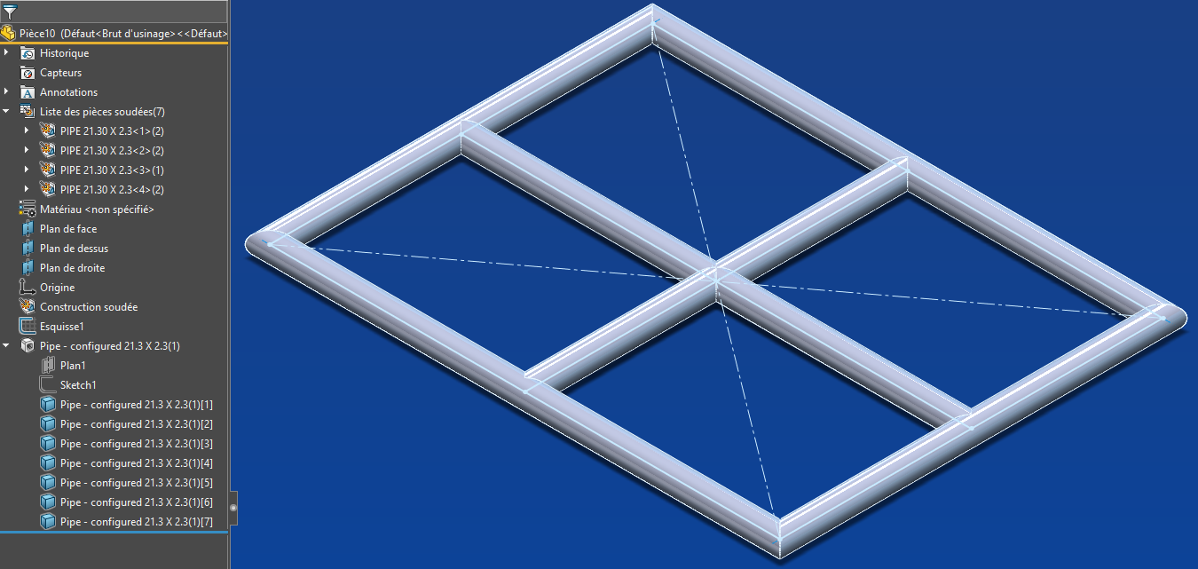
Mecanauto

Thanks @Sylk, it's true that it can help to know the functions to use, but you will always have to rework the code.

Yes it's a very relevant question, and you're absolutely right, and manage the import in an assembly with a userform to modify the global variables.

Because this mechanically welded part, I would like after importing the first one into the assembly to make it either a symmetry or a repetition and automate the import of sheet metal that will be applied on the mechanically welded frames.

So do you have an example of importing a part into an assembly with modification of the global variables?

A question at the level of equations, is it possible to display or not a sketch segment per equation?

On the other hand I was on this code to create my sketch and I can't get the segment repetition to work, could someone tell me what's wrong with my code?

Option Explicit

' Creating variable for Solidworks application
Dim swApp As SldWorks.SldWorks
' Creating variable for Solidworks document
Dim swDoc As SldWorks.ModelDoc2
' Boolean Variable
Dim Part As Object
Dim BoolStatus As Boolean
' Creating variable for Solidworks Sketch Manager
Dim swSketchManager As SldWorks.SketchManager
Dim swModelDocExt As SldWorks.ModelDocExtension

Dim hauteur As Double
Dim largeur As Double
Dim separation As Double
Dim nbSep As Integer

' Main function of our VBA program
Sub main()


hauteur = 3
largeur = 1.5
separation = 0.5
nbSep = (largeur / separation) - 1
    ' Setting Solidworks variable to Solidworks application
    Set swApp = Application.SldWorks
    Set Part = swApp.ActiveDoc
    
    
    ' Creating string type variable for storing default part location
    Dim defaultTemplate As String
    ' Setting value of this string type variable to "Default part template"
    defaultTemplate = swApp.GetUserPreferenceStringValue(swUserPreferenceStringValue_e.swDefaultTemplatePart)

    ' Setting Solidworks document to new part document
    Set swDoc = swApp.NewDocument(defaultTemplate, 0, 0, 0)
    Set swModelDocExt = swDoc.Extension
    ' Selecting Front Plane
    BoolStatus = Part.Extension.SelectByID2("Line5@Esquisse1", "EXTSKETCHSEGMENT", 0, 0, 0, False, 0, Nothing, 0)
    
    ' Setting Sketch manager for our sketch
    Set swSketchManager = swDoc.SketchManager
    
    ' Creating Variable for Solidworks Sketch segment
    Dim mySketchSegment As SketchSegment
    
    ' Inserting a sketch into selected plane
    swSketchManager.InsertSketch True
    
    ' Creating an horizontal line
    Set mySketchSegment = swSketchManager.CreateLine(0, 0, 0, largeur, 0, 0)
    Set mySketchSegment = swSketchManager.CreateLine(largeur, 0, 0, largeur, hauteur, 0)
    Set mySketchSegment = swSketchManager.CreateLine(largeur, hauteur, 0, 0, hauteur, 0)
    Set mySketchSegment = swSketchManager.CreateLine(0, hauteur, 0, 0, 0, 0)
    Set mySketchSegment = swSketchManager.CreateLine(separation, 0, 0, separation, hauteur, 0)
    BoolStatus = swModelDocExt.SelectByID2("Line5@Esquisse1", "EXTSKETCHSEGMENT", 0, separation, 0, False, 0, Nothing, 0)
    BoolStatus = swSketchManager.CreateLinearSketchStepAndRepeat(nbSep, 1, separation, 0.1, 0, 0, "", True, False, False, True, False)
    'Stop
    ' De-select the line after creation
    swDoc.ClearSelection2 True


    Set Part = swApp.ActiveDoc

    ' Zoom To Fit
    swDoc.ViewZoomtofit2
    Part.SketchManager.InsertSketch True
End Sub

In terms of repetition, it's good I found:

Option Explicit

' Creating variable for Solidworks application
Dim swApp As SldWorks.SldWorks
' Creating variable for Solidworks document
Dim swDoc As SldWorks.ModelDoc2
' Boolean Variable
Dim Part As Object
Dim BoolStatus As Boolean
' Creating variable for Solidworks Sketch Manager
Dim swSketchManager As SldWorks.SketchManager
Dim swModelDocExt As SldWorks.ModelDocExtension

Dim hauteur As Double
Dim largeur As Double
Dim separationVerticale As Double
Dim separationHorizontale As Double
Dim nbSepVert As Integer
Dim nbSepHor As Integer

' Main function of our VBA program
Sub main()


hauteur = 3
largeur = 1.5
separationVerticale = 0.5
nbSepVert = (largeur / separationVerticale) - 1
nbSepHor = hauteur / 500
If nbSepVert - Fix(nbSepVert) <> 0 Then nbSepVert = nbSepVert + 1
separationHorizontale = hauteur / nbSepVert

    ' Setting Solidworks variable to Solidworks application
    Set swApp = Application.SldWorks
    Set Part = swApp.ActiveDoc
    
    
    ' Creating string type variable for storing default part location
    Dim defaultTemplate As String
    ' Setting value of this string type variable to "Default part template"
    defaultTemplate = swApp.GetUserPreferenceStringValue(swUserPreferenceStringValue_e.swDefaultTemplatePart)

    ' Setting Solidworks document to new part document
    Set swDoc = swApp.NewDocument(defaultTemplate, 0, 0, 0)
    Set swModelDocExt = swDoc.Extension
    ' Selecting Front Plane
    BoolStatus = Part.Extension.SelectByID2("Line5@Esquisse1", "EXTSKETCHSEGMENT", 0, 0, 0, False, 0, Nothing, 0)
    
    ' Setting Sketch manager for our sketch
    Set swSketchManager = swDoc.SketchManager
    
    ' Creating Variable for Solidworks Sketch segment
    Dim mySketchSegment As SketchSegment
    
    ' Inserting a sketch into selected plane
    swSketchManager.InsertSketch True
    
    ' Creating an horizontal line
    Set mySketchSegment = swSketchManager.CreateLine(0, 0, 0, largeur, 0, 0)
    Set mySketchSegment = swSketchManager.CreateLine(largeur, 0, 0, largeur, hauteur, 0)
    Set mySketchSegment = swSketchManager.CreateLine(largeur, hauteur, 0, 0, hauteur, 0)
    Set mySketchSegment = swSketchManager.CreateLine(0, hauteur, 0, 0, 0, 0)
    Set mySketchSegment = swSketchManager.CreateLine(separationVerticale, 0, 0, separationVerticale, hauteur, 0)
    BoolStatus = swModelDocExt.SelectByID2("Ligne5", "EXTSKETCHSEGMENT", 0, separationVerticale, 0, False, 0, Nothing, 0)
    'Stop
    BoolStatus = swSketchManager.CreateLinearSketchStepAndRepeat(nbSepVert, 1, separationVerticale, 1, 0, 1.57, "", True, False, False, True, False)
    'Stop
    ' De-select the line after creation
    swDoc.ClearSelection2 True


    Set Part = swApp.ActiveDoc

    ' Zoom To Fit
    swDoc.ViewZoomtofit2
    Part.SketchManager.InsertSketch True
End Sub

These two questions remain:

Hello

The advantage of an advanced age is that you have a library rich in macros. By picking pieces here and there and adapting as needed, a macro is quickly created (see attached Zip file).
To be tested without moderation.

GrilleSoudee.zip (455.1 KB)

To answer your questions about " importing a part into an assembly with modification of the global variables " and whether or not it is possible to " display or not a sketch segment by equation ", I am tempted to answer YES...
Most constructs and methods in Solidworks are macro-enabled.
That being said, a macro is especially justified to carry out repetitive and time-consuming tasks. Is this the case for your project?

Kind regards.

1 Like

Thank you @m.blt,

For this superb well documented macro, which will allow me to complete some functions of mine which has a slightly different need.

As for the time saving, I can answer you yes, because already the automation of welded construction will save me a little time, but in the end it is with the sequel that I will save even more
.
Because on this welded construction in an assembly I want to import sheets of width defined by the welded grid (hence the importance of importing into an assembly and modifying global variables) and manage their configuration according to their position on this welded grid.

This macro will save me time on the construction of these elements, but also on the calculation of the dimension of each element compared to the global dimensions.

So if you have something that deals with these two points, I'm all for it.

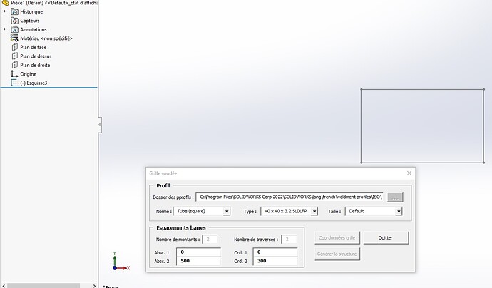
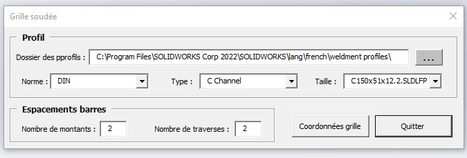
A small problem when experimenting with your macro, it doesn't generate the structure and I think that some comboboxes don't have the right values.
Because in standards I should find ISO and not the type of profiles, my file may not be constituted like yours.
I have to select the standard in the path to fill the comboboxes...

I should be able to modify it for it to work, but if others by downloading it get stuck, I preferred to warn you that I didn't have the expected result.

I rather think that you should set the profiles folder to " weldment profiles ", not one of its subfolders.

Since the size is a folder of the type that is a standard folder which is a profiles folder, if you select the standard folder instead of the profiles folder, the whole cascade is offset.

1 Like

To support the relevant message of @Sylk ...
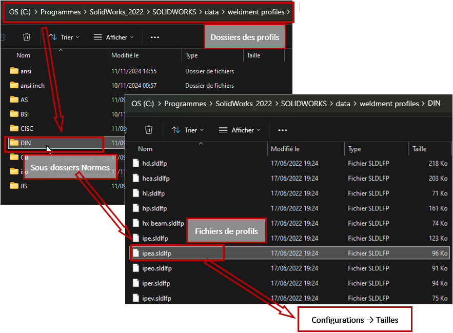
Profile sketches are organized as follows:

1- The general file of profiles, in which are...
2- The subfolders of standards (ISO, ANSI, etc.), in which are located...
3- Files defining the types of profiles (*.sldlfp), in which
Are...
4- Sketches of the profiles whose configurations correspond to their different sizes.

It is Folder n°1 that must be filled in in the upper entry box. From this, the drop-down lists for selecting standards, types and sizes are derived.
In principle, this folder n°1 is the one in the " File Locations" of the " System > Options" of Solidworks, usually retrieved in the input box when the macro is launched.

Macro obviously does not have all the necessary safeguards.
And while writing these lines, I tell myself that if the profile file is saved in a personal folder that does not respect this organization, the macro does not allow you to find it. Grrr! :face_with_symbols_over_mouth:

1 Like

I thought we could launch a 2022 macro on a SW 2020 but no... Apparently we need bookstores 2022. I guess there must be a command in the code that requires it.

Edit:

This variable (swFileLocationsWeldmentProfiles) for initializing the contents of the textbox must not exist in the 2020:

UserForm1.TextBoxProfil.Text = swApp.GetUserPreferenceStringValue(swFileLocationsWeldmentProfiles)

So I replaced it with a hard empty string

UserForm1.TextBoxProfil.Text = ""

Ah, and here too:

With folderDialog
        .InitialFileName = ""

A safeguard could be to test if the command is invalid, to initialize the root or an empty string. For backward compatibility.

EDIT:
Well, the swDocPART variable is also a problem for me...

Set swDoc = swApp.OpenDoc6(filePath, swDocPART, swOpenDocOptions_Silent, "", 0, 0)    ' Ouvre le fichier en arrière-plan

Hello @Sylk,

Macros are not normally linked to SW versions in the same way that assembly or part files are.
The only restriction is that some API properties or methods change over time, and an older version of SW may not recognize them.
It is often enough to go back one or two units in the final digit to find the previous function (OpenDoc4 is the version preceding OpenDoc6).

For the swDocPart constant:

  • If the SolidWorks API Type Library is referenced in Tools > References, VBA automatically imports the API constants, which can be used by their abbreviated names (swDocPart only).
  • If the library is not referenced, the qualified name must be used: swDocumentTypes_e.swDocPart

As for testing lines using API functions, it would be cumbersome to manage, it would take a lot of time and it would make the code less readable.
And what to do in case of a mistake, if not to get out of the macro?
On the other hand, I agree to test user input, as much as possible...

To conclude, I'm going to take a look at this profile file thing.

1 Like

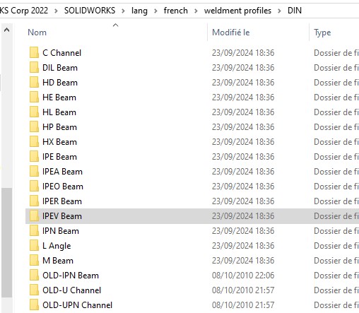
My file is the right one:

Screenshot_57

I just manually added ISO so that the comboboxes don't stay empty.

Your set of profiles should be structured as below?

image

On my SW 2022 version, the folder is as follows:
C:\Program Files\SolidWorks_2022\SOLIDWORKS\data\weldment profiles
image
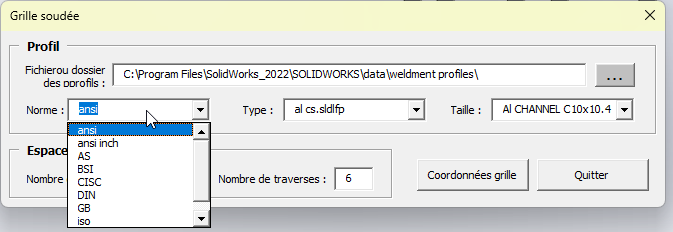
The text is displayed in the input box when the macro is launched, but you have to click on the button and accept the folder to complete the lists of standards, types and sizes.

You don't have to add anything by hand...

I understood the problem, it's that the folder is not loaded at startup, it is only loaded after choosing it in the dialog.

You have to add this to load the contents of the comboboxes at launch:

    UserForm1.TextBoxProfil.Text = swApp.GetUserPreferenceStringValue(swFileLocationsWeldmentProfiles) & "\"
    UserForm1.Show
    
    If UserForm1.TextBoxProfil.Text <> "" Then
        dossierProfils = UserForm1.TextBoxProfil.Text
        UserForm1.DossiersNormesProfils
        UserForm1.ComboBoxNorme.Enabled = True
    End If

either

    With UserForm1
      .TextBoxProfil.Text = swApp.GetUserPreferenceStringValue(swFileLocationsWeldmentProfiles) & "\"
      .Show
      If .TextBoxProfil.Text <> "" Then
          dossierProfils = .TextBoxProfil.Text
          .DossiersNormesProfils
          .ComboBoxNorme.Enabled = True
      End If
    End With

On the other hand, at home it is very slow when loading the profile, it should be able to load the sizes only on confirmation. Maybe a " load sizes " button. Unless there is a method to extract the configs without opening the file?

Thank you, I had activated the libraries but for some unknown reason, they were unchecked...

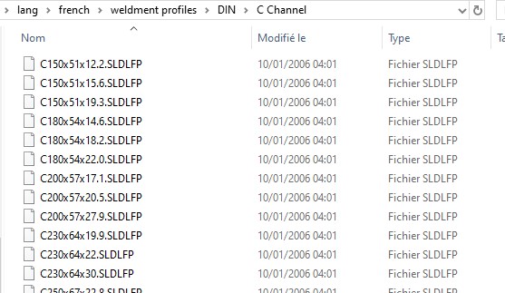
I don't have the same folder architecture as you @m.blt.
Because in the DIN folder I don't have a .sldfp file but profile type folders and in these profile type folders I have the files with .sldfp extension.

Screenshot_58

Screenshot_59

I recalibrated the code according to my architecture:

Screenshot_60

On the other hand, do you have something on the subject below because I am struggling to try to import a part file into a new assembly: