Makro solidworks do generowania konstrukcji spawanych

Cze wszystkim

Szukam fragmentu kodu, który pozwoli mi wygenerować konstrukcję spawaną.
Mam do stworzenia struktury rurowe, które są do siebie bardzo podobne.

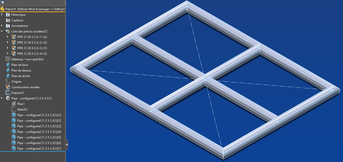
Konstrukcje rurowe są zawsze zespołem rur w tej samej płaszczyźnie, konstrukcja ta jest zawsze prostokątna i ma szereg poziomych i pionowych rur oddalonych od siebie o mniej niż 500 mm.

Chciałbym mieć kod dla bazy roboczej, która generuje szkic podstawowy i nakłada rury na ten szkic.

Oto przykład tego, co chcę utworzyć dla każdego makra:

Myślę, że podstawa z ramką to krzyżyk pośrodku, powinna mi wystarczyć, aby zautomatyzować resztę, ale biorę wszystko, co możesz wymyślić.
Bo nigdy nie tworzyłem konstrukcji makrospawanej.

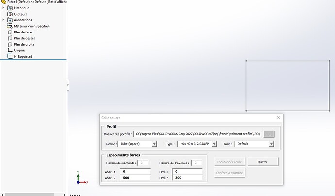
Zastanawiam się nad przejściem przez UserForm, aby wprowadzić moje podstawowe dane, a następnie wygenerować strukturę.

Mam nadzieję, że wyraziłem się wystarczająco jasno, w przeciwnym razie nie wahaj się mnie zapytać.

Dostałem ten kod, który pozwala na stworzenie konstrukcji spawanej dzięki istniejącemu szkicowi.

Problem polega na tym, że kiedy uruchamiam kod ze szkicem, który ma 6 segmentów, jest tylko 5, które wchodzą w konstrukcję spawaną.
Wydaje się to oczywiste, ponieważ " i=1 ".
Jednak gdy wstawię i=0, kod już nie działa, nie powstaje już żadna lutowana konstrukcja.

Kod z i=1:

Dim swApp As SldWorks.SldWorks
Dim Part As ModelDoc2
Dim boolstatus As Boolean
Dim FeatMgr As FeatureManager
Dim SelMgr As SelectionMgr
Dim mySketch As SldWorks.Sketch
Dim swWeldFeat As SldWorks.Feature
Dim swWeldFeatData As SldWorks.StructuralMemberFeatureData
Dim skSegCount As Long
Dim vSkSegments As Variant
Dim skSegment As SldWorks.SketchSegment
Dim i As Integer

Option Explicit

Public Sub Main()

    Set swApp = Application.SldWorks
    Set Part = swApp.ActiveDoc
    Set FeatMgr = Part.FeatureManager
    Set SelMgr = Part.SelectionManager

    Dim myFeature2 As Object
    Set myFeature2 = Part.FeatureByName("NdM 3D")
    Set mySketch = myFeature2.GetSpecificFeature2()
    vSkSegments = mySketch.GetSketchSegments()
    skSegCount = UBound(vSkSegments)
    Debug.Print "    nombre de segments dans l'esquisse = " & skSegCount
    
    Dim myFeature As Object
    Set myFeature = Part.FeatureManager.InsertWeldmentFeature()
    Dim GroupArray() As Object
    ReDim GroupArray(0 To 100) As Object
    
    For i = 1 To UBound(vSkSegments)
        Dim Group As StructuralMemberGroup
        Set Group = FeatMgr.CreateStructuralMemberGroup
        Dim Segments(0) As Object
        boolstatus = Part.Extension.SelectByID2("Line" & i & "@NdM 3D", "EXTSKETCHSEGMENT", 0, 0, 0, False, 0, Nothing, 0)
        Set Segments(0) = SelMgr.GetSelectedObject6(1, 0)
        Debug.Print "  Sketch = " & vSkSegments(i-1).GetName
        Debug.Print "  Sketch = " & vSkSegments(i-1).GetLength
        Group.Segments = (Segments)
        Set GroupArray(i-1) = Group
    Next i

    Set myFeature = Part.FeatureManager.InsertStructuralWeldment4("C:\Program Files\SOLIDWORKS Corp 2022\SOLIDWORKS\lang\french\weldment profiles\ISO\Tube (square)\40 x 40 x 3.2.sldlfp", 1, False, (GroupArray))
    Part.ClearSelection2 True

End Sub

Kod z i=0:

Dim swApp As SldWorks.SldWorks
Dim Part As ModelDoc2
Dim boolstatus As Boolean
Dim FeatMgr As FeatureManager
Dim SelMgr As SelectionMgr
Dim mySketch As SldWorks.Sketch
Dim swWeldFeat As SldWorks.Feature
Dim swWeldFeatData As SldWorks.StructuralMemberFeatureData
Dim skSegCount As Long
Dim vSkSegments As Variant
Dim skSegment As SldWorks.SketchSegment
Dim i As Integer

Option Explicit

Public Sub Main()

    Set swApp = Application.SldWorks
    Set Part = swApp.ActiveDoc
    Set FeatMgr = Part.FeatureManager
    Set SelMgr = Part.SelectionManager

    Dim myFeature2 As Object
    Set myFeature2 = Part.FeatureByName("NdM 3D")
    Set mySketch = myFeature2.GetSpecificFeature2()
    vSkSegments = mySketch.GetSketchSegments()
    skSegCount = UBound(vSkSegments)
    Debug.Print "    nombre de segments dans l'esquisse = " & skSegCount
    
    Dim myFeature As Object
    Set myFeature = Part.FeatureManager.InsertWeldmentFeature()
    Dim GroupArray() As Object
    ReDim GroupArray(0 To 100) As Object
    
    For i = 0 To UBound(vSkSegments)
        Dim Group As StructuralMemberGroup
        Set Group = FeatMgr.CreateStructuralMemberGroup
        Dim Segments(0) As Object
        boolstatus = Part.Extension.SelectByID2("Line" & i & "@NdM 3D", "EXTSKETCHSEGMENT", 0, 0, 0, False, 0, Nothing, 0)
        Set Segments(0) = SelMgr.GetSelectedObject6(1, 0)
        Debug.Print "  Sketch = " & vSkSegments(i).GetName
        Debug.Print "  Sketch = " & vSkSegments(i).GetLength
        Group.Segments = (Segments)
        Set GroupArray(i) = Group
    Next i

    Set myFeature = Part.FeatureManager.InsertStructuralWeldment4("C:\Program Files\SOLIDWORKS Corp 2022\SOLIDWORKS\lang\french\weldment profiles\ISO\Tube (square)\40 x 40 x 3.2.sldlfp", 1, False, (GroupArray))
    Part.ClearSelection2 True

End Sub

Oto plik używany do testowania:
Głośnik 3D.SLDPRT (42.5 KB)

Dla powyższego problemu z kodem znalazłem rozwiązanie, problem z nazwą segmentu:

Dim swApp As SldWorks.SldWorks
Dim Part As ModelDoc2
Dim boolstatus As Boolean
Dim FeatMgr As FeatureManager
Dim SelMgr As SelectionMgr
Dim mySketch As SldWorks.Sketch
Dim swWeldFeat As SldWorks.Feature
Dim swWeldFeatData As SldWorks.StructuralMemberFeatureData
Dim skSegCount As Long
Dim vSkSegments As Variant
Dim skSegment As SldWorks.SketchSegment
Dim i As Integer

Option Explicit

Public Sub Main()

    Set swApp = Application.SldWorks
    Set Part = swApp.ActiveDoc
    Set FeatMgr = Part.FeatureManager
    Set SelMgr = Part.SelectionManager

    Dim myFeature2 As Object
    Set myFeature2 = Part.FeatureByName("NdM 3D")
    Set mySketch = myFeature2.GetSpecificFeature2()
    vSkSegments = mySketch.GetSketchSegments()
    skSegCount = UBound(vSkSegments)
    Debug.Print "    nombre de segments dans l'esquisse = " & skSegCount
    
    Dim myFeature As Object
    Set myFeature = Part.FeatureManager.InsertWeldmentFeature()
    Dim GroupArray() As Object
    ReDim GroupArray(0 To 100) As Object
    
    For i = 0 To UBound(vSkSegments)
        Dim Group As StructuralMemberGroup
        Set Group = FeatMgr.CreateStructuralMemberGroup
        Dim Segments(0) As Object
        boolstatus = Part.Extension.SelectByID2(vSkSegments(i).GetName & "@NdM 3D", "EXTSKETCHSEGMENT", 0, 0, 0, False, 0, Nothing, 0)
        Set Segments(0) = SelMgr.GetSelectedObject6(1, 0)
        Debug.Print "  Sketch = " & vSkSegments(i ).GetName
        Debug.Print "  Sketch = " & vSkSegments(i).GetLength
        Group.Segments = (Segments)
        Set GroupArray(i) = Group
        Stop
    Next i
Debug.Print "  Nb in group = " & UBound(GroupArray)
    Set myFeature = Part.FeatureManager.InsertStructuralWeldment4("C:\Program Files\SOLIDWORKS Corp 2022\SOLIDWORKS\lang\french\weldment profiles\ISO\Tube (square)\40 x 40 x 3.2.sldlfp", 1, False, (GroupArray))
    Part.ClearSelection2 True

End Sub

Zacząłem od końca, teraz muszę wymyślić, jak stworzyć szkic przez VBA!!

Nie mówiąc już o kodzie, czy testowałeś z powtórzeniami pól + małymi równaniami?

1 polubienie

Witam

Nie należy lekceważyć przydatności nagrywania makr.

Oto nagrane przeze mnie makro, które odpowiada na to żądanie:

Dim swApp As Object

Dim Part As Object
Dim boolstatus As Boolean
Dim longstatus As Long, longwarnings As Long

Sub main()

Set swApp = Application.SldWorks

Set Part = swApp.ActiveDoc
boolstatus = Part.Extension.SelectByID2("Plan de dessus", "PLANE", 0, 0, 0, False, 0, Nothing, 0)
Part.SketchManager.InsertSketch True
Part.ClearSelection2 True
boolstatus = Part.Extension.SetUserPreferenceToggle(swUserPreferenceToggle_e.swSketchAddConstToRectEntity, swUserPreferenceOption_e.swDetailingNoOptionSpecified, True)
boolstatus = Part.Extension.SetUserPreferenceToggle(swUserPreferenceToggle_e.swSketchAddConstLineDiagonalType, swUserPreferenceOption_e.swDetailingNoOptionSpecified, True)
Dim vSkLines As Variant
vSkLines = Part.SketchManager.CreateCenterRectangle(0, 0, 0, 0.222, 0.1665, 0)

' Named View
Part.ShowNamedView2 "*Isométrique", 7
Part.ViewZoomtofit2
Part.ClearSelection2 True
Dim skSegment As Object
Set skSegment = Part.SketchManager.CreateLine(-0#, -0.1665, 0#, 0#, 0.1665, 0#)
Part.ClearSelection2 True
Set skSegment = Part.SketchManager.CreateLine(-0.222, 0#, 0#, 0.222, 0#, 0#)
Part.ClearSelection2 True
Part.SketchManager.InsertSketch True
Part.ClearSelection2 True
boolstatus = Part.Extension.SelectByID2("Esquisse1", "SKETCH", 0, 0, 0, False, 0, Nothing, 0)
Dim myFeature As Object
Set myFeature = Part.FeatureManager.InsertWeldmentFeature()
boolstatus = Part.Extension.SelectByID2("Line2@Esquisse1", "EXTSKETCHSEGMENT", -0.222, -8.77585521755009E-02, 0, True, 0, Nothing, 0)
boolstatus = Part.Extension.SelectByID2("Line3@Esquisse1", "EXTSKETCHSEGMENT", -0.14708588433075, 0.1665, 0, True, 0, Nothing, 0)
boolstatus = Part.Extension.SelectByID2("Line4@Esquisse1", "EXTSKETCHSEGMENT", 0.222, 7.22480810802039E-02, 0, True, 0, Nothing, 0)
boolstatus = Part.Extension.SelectByID2("Line1@Esquisse1", "EXTSKETCHSEGMENT", 7.30118244492815E-02, -0.1665, 0, True, 0, Nothing, 0)
boolstatus = Part.Extension.SelectByID2("Line7@Esquisse1", "EXTSKETCHSEGMENT", 0, -6.42442245170969E-02, 0, True, 0, Nothing, 0)
boolstatus = Part.Extension.SelectByID2("Line8@Esquisse1", "EXTSKETCHSEGMENT", -0.148081910198584, 0, 0, True, 0, Nothing, 0)
Dim vGroups As Variant
Dim GroupArray() As Object
ReDim GroupArray(0 To 2) As Object
Dim Group1 As Object
Set Group1 = Part.FeatureManager.CreateStructuralMemberGroup()
Dim vSegement1 As Variant
Dim SegementArray1() As Object
ReDim SegementArray1(0 To 3) As Object
Part.ClearSelection2 True
boolstatus = Part.Extension.SelectByID2("Line2@Esquisse1", "EXTSKETCHSEGMENT", -0.716861233578527, 0, 7.41652842845042E-02, True, 0, Nothing, 0)
boolstatus = Part.Extension.SelectByID2("Line3@Esquisse1", "EXTSKETCHSEGMENT", -0.716861233578527, 0, 7.41652842845042E-02, True, 0, Nothing, 0)
boolstatus = Part.Extension.SelectByID2("Line4@Esquisse1", "EXTSKETCHSEGMENT", -0.716861233578527, 0, 7.41652842845042E-02, True, 0, Nothing, 0)
boolstatus = Part.Extension.SelectByID2("Line1@Esquisse1", "EXTSKETCHSEGMENT", -0.716861233578527, 0, 7.41652842845042E-02, True, 0, Nothing, 0)
Dim Segment As Object
Set Segment = Part.SelectionManager.GetSelectedObject5(1)
Set SegementArray1(0) = Segment
Set Segment = Part.SelectionManager.GetSelectedObject5(2)
Set SegementArray1(1) = Segment
Set Segment = Part.SelectionManager.GetSelectedObject5(3)
Set SegementArray1(2) = Segment
Set Segment = Part.SelectionManager.GetSelectedObject5(4)
Set SegementArray1(3) = Segment
vSegement1 = SegementArray1
Group1.Segments = (vSegement1)
Group1.ApplyCornerTreatment = True
Group1.CornerTreatmentType = 1
Group1.GapWithinGroup = 0
Group1.GapForOtherGroups = 0
Group1.Angle = 0
Set GroupArray(0) = Group1
Dim Group2 As Object
Set Group2 = Part.FeatureManager.CreateStructuralMemberGroup()
Dim vSegement2 As Variant
Dim SegementArray2() As Object
ReDim SegementArray2(0 To 0) As Object
Part.ClearSelection2 True
boolstatus = Part.Extension.SelectByID2("Line7@Esquisse1", "EXTSKETCHSEGMENT", -0.716861233578527, 0, 7.41652842845042E-02, True, 0, Nothing, 0)
Set Segment = Part.SelectionManager.GetSelectedObject5(1)
Set SegementArray2(0) = Segment
vSegement2 = SegementArray2
Group2.Segments = (vSegement2)
Group2.ApplyCornerTreatment = True
Group2.CornerTreatmentType = 1
Group2.GapWithinGroup = 0
Group2.GapForOtherGroups = 0
Group2.Angle = 0
Set GroupArray(1) = Group2
Dim Group3 As Object
Set Group3 = Part.FeatureManager.CreateStructuralMemberGroup()
Dim vSegement3 As Variant
Dim SegementArray3() As Object
ReDim SegementArray3(0 To 0) As Object
Part.ClearSelection2 True
boolstatus = Part.Extension.SelectByID2("Line8@Esquisse1", "EXTSKETCHSEGMENT", -0.716861233578527, 0, 7.41652842845042E-02, True, 0, Nothing, 0)
Set Segment = Part.SelectionManager.GetSelectedObject5(1)
Set SegementArray3(0) = Segment
vSegement3 = SegementArray3
Group3.Segments = (vSegement3)
Group3.ApplyCornerTreatment = True
Group3.CornerTreatmentType = 1
Group3.GapWithinGroup = 0
Group3.GapForOtherGroups = 0
Group3.Angle = 0
Set GroupArray(2) = Group3
vGroups = GroupArray
Set myFeature = Part.FeatureManager.InsertStructuralWeldment4("C:\Program Files\SOLIDWORKS Corp\SOLIDWORKS\lang\french\weldment profiles\iso\pipe.sldlfp", 1, True, (vGroups))
Part.ClearSelection2 True
boolstatus = Part.Extension.SelectByID2("Pipe - configured 21.3 X 2.3(1)", "BODYFEATURE", 0, 0, 0, False, 0, Nothing, 0)
Part.ClearSelection2 True
End Sub

Mecanauto_3.swp (42,5 KB)

Makro, które to generuje:
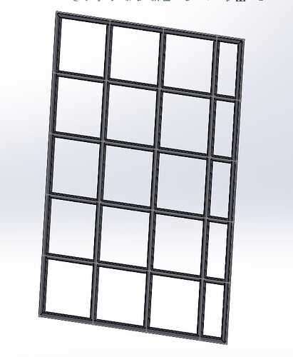
Dzięki @Sylk prawdą jest, że znajomość funkcji do użycia może być pomocna, ale zawsze będziesz musiał przerobić kod.

Tak, to bardzo istotne pytanie i masz absolutną rację, i zarządzasz importem w zestawie za pomocą formularza użytkownika, aby modyfikować zmienne globalne.

Ponieważ jest to część spawana mechanicznie, chciałbym po zaimportowaniu pierwszej do złożenia, aby była to albo symetria, albo powtórzenie i zautomatyzowano import blachy, która będzie nakładana na ramy spawane mechanicznie.

Czy masz przykład importu części do zespołu z modyfikacją zmiennych globalnych?

Pytanie na poziomie równań, czy możliwe jest wyświetlenie lub nie segmentu szkicu dla każdego równania?

Z drugiej strony byłem na tym kodzie, aby stworzyć mój szkic i nie mogę zmusić powtórzenia segmentu do działania, czy ktoś mógłby mi powiedzieć, co jest nie tak z moim kodem?

Option Explicit

' Creating variable for Solidworks application
Dim swApp As SldWorks.SldWorks
' Creating variable for Solidworks document
Dim swDoc As SldWorks.ModelDoc2
' Boolean Variable
Dim Part As Object
Dim BoolStatus As Boolean
' Creating variable for Solidworks Sketch Manager
Dim swSketchManager As SldWorks.SketchManager
Dim swModelDocExt As SldWorks.ModelDocExtension

Dim hauteur As Double
Dim largeur As Double
Dim separation As Double
Dim nbSep As Integer

' Main function of our VBA program
Sub main()


hauteur = 3
largeur = 1.5
separation = 0.5
nbSep = (largeur / separation) - 1
    ' Setting Solidworks variable to Solidworks application
    Set swApp = Application.SldWorks
    Set Part = swApp.ActiveDoc
    
    
    ' Creating string type variable for storing default part location
    Dim defaultTemplate As String
    ' Setting value of this string type variable to "Default part template"
    defaultTemplate = swApp.GetUserPreferenceStringValue(swUserPreferenceStringValue_e.swDefaultTemplatePart)

    ' Setting Solidworks document to new part document
    Set swDoc = swApp.NewDocument(defaultTemplate, 0, 0, 0)
    Set swModelDocExt = swDoc.Extension
    ' Selecting Front Plane
    BoolStatus = Part.Extension.SelectByID2("Line5@Esquisse1", "EXTSKETCHSEGMENT", 0, 0, 0, False, 0, Nothing, 0)
    
    ' Setting Sketch manager for our sketch
    Set swSketchManager = swDoc.SketchManager
    
    ' Creating Variable for Solidworks Sketch segment
    Dim mySketchSegment As SketchSegment
    
    ' Inserting a sketch into selected plane
    swSketchManager.InsertSketch True
    
    ' Creating an horizontal line
    Set mySketchSegment = swSketchManager.CreateLine(0, 0, 0, largeur, 0, 0)
    Set mySketchSegment = swSketchManager.CreateLine(largeur, 0, 0, largeur, hauteur, 0)
    Set mySketchSegment = swSketchManager.CreateLine(largeur, hauteur, 0, 0, hauteur, 0)
    Set mySketchSegment = swSketchManager.CreateLine(0, hauteur, 0, 0, 0, 0)
    Set mySketchSegment = swSketchManager.CreateLine(separation, 0, 0, separation, hauteur, 0)
    BoolStatus = swModelDocExt.SelectByID2("Line5@Esquisse1", "EXTSKETCHSEGMENT", 0, separation, 0, False, 0, Nothing, 0)
    BoolStatus = swSketchManager.CreateLinearSketchStepAndRepeat(nbSep, 1, separation, 0.1, 0, 0, "", True, False, False, True, False)
    'Stop
    ' De-select the line after creation
    swDoc.ClearSelection2 True


    Set Part = swApp.ActiveDoc

    ' Zoom To Fit
    swDoc.ViewZoomtofit2
    Part.SketchManager.InsertSketch True
End Sub

Jeśli chodzi o powtórzenia, to dobrze, że znalazłem:

Option Explicit

' Creating variable for Solidworks application
Dim swApp As SldWorks.SldWorks
' Creating variable for Solidworks document
Dim swDoc As SldWorks.ModelDoc2
' Boolean Variable
Dim Part As Object
Dim BoolStatus As Boolean
' Creating variable for Solidworks Sketch Manager
Dim swSketchManager As SldWorks.SketchManager
Dim swModelDocExt As SldWorks.ModelDocExtension

Dim hauteur As Double
Dim largeur As Double
Dim separationVerticale As Double
Dim separationHorizontale As Double
Dim nbSepVert As Integer
Dim nbSepHor As Integer

' Main function of our VBA program
Sub main()


hauteur = 3
largeur = 1.5
separationVerticale = 0.5
nbSepVert = (largeur / separationVerticale) - 1
nbSepHor = hauteur / 500
If nbSepVert - Fix(nbSepVert) <> 0 Then nbSepVert = nbSepVert + 1
separationHorizontale = hauteur / nbSepVert

    ' Setting Solidworks variable to Solidworks application
    Set swApp = Application.SldWorks
    Set Part = swApp.ActiveDoc
    
    
    ' Creating string type variable for storing default part location
    Dim defaultTemplate As String
    ' Setting value of this string type variable to "Default part template"
    defaultTemplate = swApp.GetUserPreferenceStringValue(swUserPreferenceStringValue_e.swDefaultTemplatePart)

    ' Setting Solidworks document to new part document
    Set swDoc = swApp.NewDocument(defaultTemplate, 0, 0, 0)
    Set swModelDocExt = swDoc.Extension
    ' Selecting Front Plane
    BoolStatus = Part.Extension.SelectByID2("Line5@Esquisse1", "EXTSKETCHSEGMENT", 0, 0, 0, False, 0, Nothing, 0)
    
    ' Setting Sketch manager for our sketch
    Set swSketchManager = swDoc.SketchManager
    
    ' Creating Variable for Solidworks Sketch segment
    Dim mySketchSegment As SketchSegment
    
    ' Inserting a sketch into selected plane
    swSketchManager.InsertSketch True
    
    ' Creating an horizontal line
    Set mySketchSegment = swSketchManager.CreateLine(0, 0, 0, largeur, 0, 0)
    Set mySketchSegment = swSketchManager.CreateLine(largeur, 0, 0, largeur, hauteur, 0)
    Set mySketchSegment = swSketchManager.CreateLine(largeur, hauteur, 0, 0, hauteur, 0)
    Set mySketchSegment = swSketchManager.CreateLine(0, hauteur, 0, 0, 0, 0)
    Set mySketchSegment = swSketchManager.CreateLine(separationVerticale, 0, 0, separationVerticale, hauteur, 0)
    BoolStatus = swModelDocExt.SelectByID2("Ligne5", "EXTSKETCHSEGMENT", 0, separationVerticale, 0, False, 0, Nothing, 0)
    'Stop
    BoolStatus = swSketchManager.CreateLinearSketchStepAndRepeat(nbSepVert, 1, separationVerticale, 1, 0, 1.57, "", True, False, False, True, False)
    'Stop
    ' De-select the line after creation
    swDoc.ClearSelection2 True


    Set Part = swApp.ActiveDoc

    ' Zoom To Fit
    swDoc.ViewZoomtofit2
    Part.SketchManager.InsertSketch True
End Sub

Pozostają jeszcze te dwa pytania:

Witam

Zaletą zaawansowanego wieku jest to, że masz bibliotekę bogatą w makra. Wybierając kawałki tu i ówdzie i dostosowując w razie potrzeby, szybko tworzy się makro (patrz załączony plik Zip).
Do testowania bez umiaru.

GrilleSoudee.zip (455,1 KB)

Aby odpowiedzieć na Twoje pytania dotyczące " importowania części do zespołu z modyfikacją zmiennych globalnych " i czy możliwe jest " wyświetlenie lub nie segmentu szkicu za pomocą równania ", kusi mnie, aby odpowiedzieć TAK...
Większość konstrukcji i metod w Solidworks obsługuje makra.
Biorąc to pod uwagę, makro jest szczególnie uzasadnione do wykonywania powtarzalnych i czasochłonnych zadań. Czy tak jest w przypadku Twojego projektu?

Pozdrowienia.

1 polubienie

Dziękuję @m_blt,

Do tego znakomite dobrze udokumentowane makro, które pozwoli mi na wykonanie niektórych moich funkcji, które mają nieco inną potrzebę.

Jeśli chodzi o oszczędność czasu, to mogę Wam odpowiedzieć tak, bo już automatyzacja konstrukcji spawanych pozwoli mi zaoszczędzić trochę czasu, ale w końcu to z sequelem zaoszczędzę jeszcze więcej
.
Ponieważ na tej spawanej konstrukcji w zespole chcę zaimportować arkusze o szerokości zdefiniowanej przez spawaną siatkę (stąd znaczenie importu do zespołu i modyfikowania zmiennych globalnych) i zarządzać ich konfiguracją zgodnie z ich położeniem na tej spawanej siatce.

To makro pozwoli mi zaoszczędzić czas na budowie tych elementów, ale także na obliczeniach wymiaru każdego elementu w porównaniu z wymiarami globalnymi.

Więc jeśli masz coś, co dotyczy tych dwóch punktów, jestem za tym.

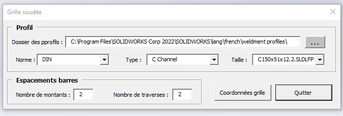
Mały problem podczas eksperymentowania z makrem, nie generuje struktury i myślę, że niektóre listy rozwijalne nie mają odpowiednich wartości.
Ponieważ w standardach powinienem znaleźć ISO, a nie typ profili, mój plik może nie być utworzony tak jak Twój.
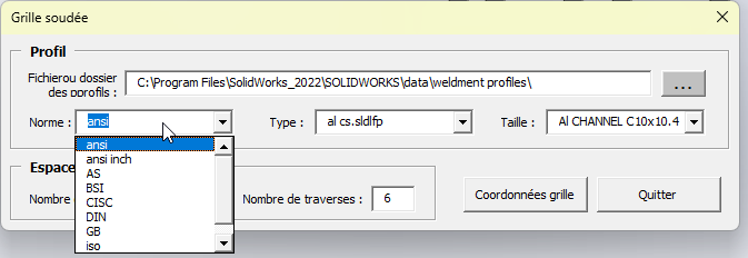
Muszę wybrać standard w ścieżce, aby wypełnić listy rozwijane...

Powinienem być w stanie go zmodyfikować, aby działał, ale jeśli inni pobierając go utkną, wolałem ostrzec, że nie osiągnąłem oczekiwanego rezultatu.

Myślę raczej, że powinieneś ustawić folder profiles na "  profile spawane ", a nie jeden z jego podfolderów.

Ponieważ rozmiar jest folderem typu folder, który jest folderem standardowym, który jest folderem profili, jeśli wybierzesz folder standardowy zamiast folderu profili, cała kaskada zostanie przesunięta.

1 polubienie

Aby wesprzeć odpowiednie przesłanie @Sylk ...
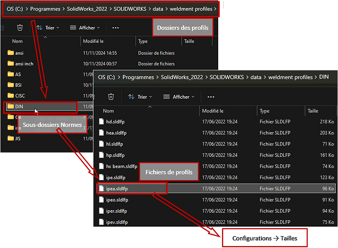
Szkice profilu są zorganizowane w następujący sposób:

1- Ogólny plik profili, w którym znajdują się...
2- Podfoldery norm (ISO, ANSI itp.), W których znajdują się...
3- Pliki definiujące typy profili (*.sldlfp), w których
Są...
4- Szkice profili, których konfiguracje odpowiadają ich różnym rozmiarom.

Jest to folder nr 1 , który należy wypełnić w górnym polu wprowadzania. Na tej podstawie pochodzą listy rozwijane do wyboru standardów, typów i rozmiarów.
Zasadniczo, ten folder nr 1 to folder w " Lokalizacjach plików " w " Opcjach > systemowych " Solidworks, zwykle pobierany w polu wprowadzania po uruchomieniu makra.

Makro oczywiście nie posiada wszystkich niezbędnych zabezpieczeń.
I pisząc te wiersze, mówię sobie, że jeśli plik profilu jest zapisany w folderze osobistym, który nie szanuje tej organizacji, makro nie pozwala go znaleźć. Grrr! :face_with_symbols_over_mouth:

1 polubienie

Myślałem, że możemy uruchomić makro 2022 na SW 2020, ale nie... Widocznie księgarnie 2022 są nam potrzebne. Domyślam się, że w kodzie musi być polecenie, które tego wymaga.

Redagować:

Ta zmienna (swFileLocationsWeldmentProfiles) służąca do inicjalizacji zawartości pola tekstowego nie może istnieć w 2020 roku:

UserForm1.TextBoxProfil.Text = swApp.GetUserPreferenceStringValue(swFileLocationsWeldmentProfiles)

Zastąpiłem go więc twardym pustym sznurkiem

UserForm1.TextBoxProfil.Text = ""

Ach, i tu też:

With folderDialog
        .InitialFileName = ""

Zabezpieczeniem może być sprawdzenie, czy polecenie jest nieprawidłowe, zainicjowanie katalogu głównego lub pustego ciągu. Dla kompatybilności wstecznej.

REDAGOWAĆ:
No cóż, zmienna swDocPART też jest dla mnie problemem...

Set swDoc = swApp.OpenDoc6(filePath, swDocPART, swOpenDocOptions_Silent, "", 0, 0)    ' Ouvre le fichier en arrière-plan

Witaj @Sylk,

Makra nie są zwykle łączone z wersjami oprogramowania w taki sam sposób, jak pliki zespołów lub części.
Jedynym ograniczeniem jest to, że niektóre właściwości lub metody API zmieniają się z czasem, a starsza wersja oprogramowania może ich nie rozpoznawać.
Często wystarczy cofnąć się o jedną lub dwie jednostki w ostatniej cyfrze, aby znaleźć poprzednią funkcję (OpenDoc4 to wersja poprzedzająca OpenDoc6).

Dla stałej swDocPart :

  • Jeżeli w Narzędziach > odniesieniach znajduje się biblioteka typów API SolidWorks, VBA automatycznie importuje stałe API, które mogą być używane przez ich skrócone nazwy (tylko swDocPart).
  • Jeśli biblioteka nie jest przywoływana, należy użyć nazwy kwalifikowanej: swDocumentTypes_e.swDocPart

Jeśli chodzi o testowanie linii za pomocą funkcji API, byłoby to kłopotliwe w zarządzaniu, zajęłoby dużo czasu i sprawiłoby, że kod byłby mniej czytelny.
A co zrobić w przypadku pomyłki, jeśli nie wyjścia z makro?
Z drugiej strony zgadzam się na testowanie danych wejściowych użytkownika, w miarę możliwości...

Na zakończenie przyjrzę się temu plikowi profilowemu.

1 polubienie

Mój plik jest właściwy:

Screenshot_57

Właśnie ręcznie dodałem ISO, aby listy rozwijalne nie pozostały puste.

Twój zestaw profili powinien być skonstruowany jak poniżej?

W mojej wersji SW 2022 folder wygląda następująco:
C:\Program Files\SolidWorks_2022\SOLIDWORKS\data\profile konstrukcji spawanej
image
Tekst jest wyświetlany w polu wprowadzania po uruchomieniu makra, ale musisz kliknąć przycisk i zaakceptować folder, aby uzupełnić listy standardów, typów i rozmiarów.

Nie musisz niczego dodawać ręcznie...

Zrozumiałem problem, polega on na tym, że folder nie jest ładowany podczas uruchamiania, jest ładowany dopiero po wybraniu go w oknie dialogowym.

Musisz to dodać, aby załadować zawartość list rozwijanych podczas uruchamiania:

    UserForm1.TextBoxProfil.Text = swApp.GetUserPreferenceStringValue(swFileLocationsWeldmentProfiles) & "\"
    UserForm1.Show
    
    If UserForm1.TextBoxProfil.Text <> "" Then
        dossierProfils = UserForm1.TextBoxProfil.Text
        UserForm1.DossiersNormesProfils
        UserForm1.ComboBoxNorme.Enabled = True
    End If

albo

    With UserForm1
      .TextBoxProfil.Text = swApp.GetUserPreferenceStringValue(swFileLocationsWeldmentProfiles) & "\"
      .Show
      If .TextBoxProfil.Text <> "" Then
          dossierProfils = .TextBoxProfil.Text
          .DossiersNormesProfils
          .ComboBoxNorme.Enabled = True
      End If
    End With

Z drugiej strony w domu ładowanie profilu jest bardzo powolne, powinien być w stanie załadować rozmiary dopiero po potwierdzeniu. Może przycisk " rozmiary ładunku ". Chyba, że istnieje metoda na wyodrębnienie configów bez otwierania pliku?

Dziękuję, aktywowałem biblioteki, ale z jakiegoś nieznanego powodu nie zostały one zaznaczone...

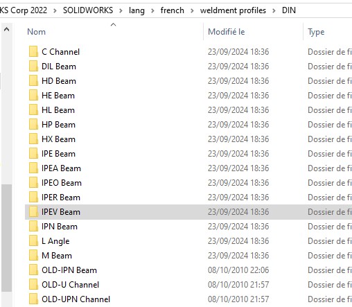
Nie mam takiej samej architektury folderów jak Ty @m_blt.
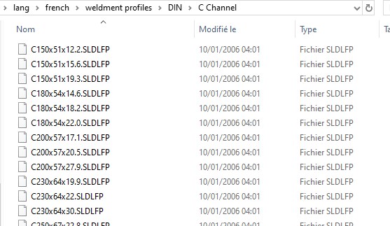
Ponieważ w folderze DIN nie mam pliku .sldfp, ale foldery typu profile i w tych folderach typu profilu mam pliki z rozszerzeniem .sldfp.

Screenshot_58

Screenshot_59

Ponownie skalibrowałem kod zgodnie z moją architekturą:

Screenshot_60

Z drugiej strony, czy masz coś na ten temat poniżej, ponieważ mam problem z próbą zaimportowania pliku części do nowego zespołu: