Document Model Upgrade and Solidworks Setup

Hello everyone,

I am currently working on a complete overhaul of our drawing standards in SolidWorks, and I am looking for feedback and best practices.

Today, we use models (plans, cartridges, nomenclatures) that are quite old and are no longer reliable. The objective is therefore to start again on a clean, coherent and sustainable basis.

->Context:
Using SolidWorks without PDM (Work on a Shared Network):

-> Main activities:
sheet metal work (with folded/unfolded tops)
Machining
Mechanically welded (structures + multibody)
Commercial Components
Using Custom Properties Through the SolidWorks Form

->What I'm putting in place:

Model of parts / assemblies / drawings
Cartridges with automatic fields (mass, material, index, etc.)

->Differentiation of formats:

A4 → mass in grams, odds to 1 decimal place

A3 / A1 / A0 → mass in kg, odds without decimal places

->Dedicated drawings:

A4 sheet metal (with unfolded view + dimensions L / W / thickness)
A4 machining

->Points on which I would like your feedback:

What custom properties do you use as standard?
How do you properly manage sheet metal information (unfolded, thickness, etc.) in the cartridge?
Do you have any tips for making bills of materials without PDM more reliable?
How do you structure your library of mechanically welded profiles?
Do you have any automations in place (macros, advanced forms, etc.)?

I am interested in any documentation, model examples, or advice from your field experience.

Thank you in advance for your help

Hello

For BOMs. We use what we call " a dedicated assembly".
The idea is to repatriate in an assembly, sub-assemblies that are just necessary for the drawing. We create an environment assembly (excluded from the BOM), and a " manufacturing " assembly where we compose the BOM elements. We bring up what is necessary to the first level or not.
Our assemblies and parts have properties that we fill in on the side tab dedicated to the personal property, (Manufacturing - trade) which allow us to sort in the nomenclature:
2 commercial items - engine, screws, etc...
Manufacturing - mechanic, piping, machining etc...

Important information: we work in SKELETON mode. When composing our dedicated assemblies, we do not co-drive our sub-assemblies, we fix them directly from origin to origin during insertion. No error and assembly and light MEP.

No other piece of information to identify the part (description-mass-material, etc.)
We have several nomenclatures.
plan set = BOM Manufacturing, BOM trade
Detail plan = summary nomenclature (A3 plan for the most part, A2 A1 A0 for large frames)
Detailed plan = Mechanical-welded nomenclature, we have two types,
multi-body in this case description, material, weight, thickness of sheet metal or CAE, HEA etc
Another nomenclature is identical, but our mechanically welded is built one body per piece in an assembly.

We do not use a mechanically welded library, we prefer blocks that we import directly into our sketches. This avoids the need to provide libraries when exporting natives.

We just use macros to extract a list of parts where we fill in the properties of custom (description, standards, etc.), and another macro to reinject them into the different parts or assembly.

Identify the needs of past projects, define a working method (If not, it's a free-for-all). The needs of the bills of materials change very little on a project. It is always possible to add a column in your BOM templates, and custom properties in your assemblies and parts later.

1 Like

Thank you, for this feedback, I'll take it into account, however, I don't know how to set by default on an A3 format the fact that all the dimensions will be without decimal, do you have any feedback on this?

Sincerely,

Hello,

Be aware that in a SolidWorks drawing, there are 3 layers:

  1. The drawing file - defined through the .slddrw extension
  2. Basemap - is the first essential view in the file through which the size/format of the plan is defined
  3. the standard of dressing.

When you create a .drwdot model, it brings together the 3 layers and can also integrate additional elements (predefined view, table, annotation block).

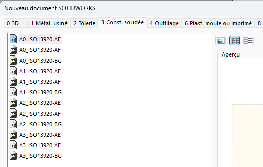
You can associate a different wrapping standard with an A3 file + basemap that specifies that the dimensions are rounded to the nearest integer.

For my part:
One basemap per format (A4, A3, A2, A1, A0) with the frame, ruler and title block as a linked sketch block (so that an update of the cartridge block automatically deploys for each drawing taken in editing)

Several models using these basemaps and completed with tables and/or annotation blocks and predefined view according to the type of part (sheet metal, welded construction, machining part, 3D printing, etc.)

Create subfolders to categorize:
image

2 Likes

Hello, a revision table with the index that is automatically set to a box in the cartouche can be useful

1 Like

Hello SILVER, can you tell me a little more about the cartridge in block form? In our current drawings, our cartridges are drawn on the background plan and therefore horrible to change.

Your database seems to me to be really complete and well worked. So your sheet metal drawings have predefined views?

Can you show me how your part/assembly files break down? It will surely give me a different vision from ours.

Thank you for your help.

For the Sketch Block Block:
You trace your cartridge using line and do not hesitate to dimension everything and constrain. Place your " label " annotation and your " attribute " annotation ($PRPSHEET:"  " to call the properties of the referenced 3D | example $PRPSHEET:" mass "; $PRP:"  " to call the properties of the drawing itself | example $PRP:" Plan No.")

Select everything and define a block that you save somewhere.

Insert this sketch frame while keeping the link in your baseplane.
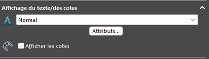
To not see the dimensions of the title block, in the Text/Dimension Display section, use these settings:
image

All of our plans have at least 2 predefined views:
The Isometric view is an empty view for general annotations.
My recommendation is to never leave a note on the sheet because a note attached to the sheet is treated in the same way as the annotations of the basemap (reminder: basemap = 1st view of the drawing).

The sheet metal drawing also has a predefined view for flattening to be sure that it is present.

Not sure you understand what you want to know...

We have 2 part models (1 with units in g, the second in kg), 3 assembly models (1 layout with a defined floor plan, 1 Module/Machine with connection resources and published floor plan and 1 functional group without published resources).

An example:
LLB-PRT-MECA A3.zip (123.8 KB)

1 Like

According to the activity you describe, PDM would not be a luxury.

1 Like

And it's so convenient!!
Nothing but the project sheets (cartridge pre-filled in one click)
Well, you have to manage it :face_with_peeking_eye: