Hello.
Until now, I used SW for fairly simple mechanical parts.
The basic drawing and dimensioning in SW was more than enough for me.
I now need to make drawings with a Civil Engineering / Architecture dimension style:
- see queues (how to make queues in SW? make a sketch dedicated to that?
- have a rating system showing an elevation.
-how to make a ground plan in solidworks, how to use an aerial view in SW?
-If anyone has an example of an archi / GC plan in sw, I'll be interested.
Thank you
Have a nice day.
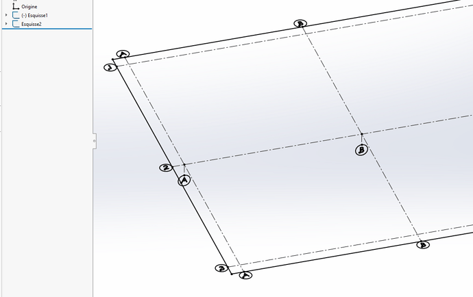
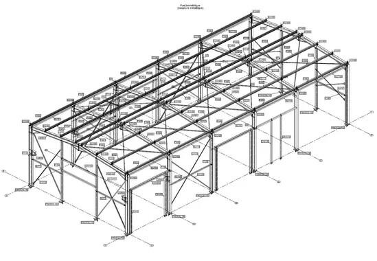
@stefbeno the " files " are the discontinuous lines named from 1 to x for example and from A to y for example drawn for the alignment of the different columns. (see ISO image as an example)
No known solution for me to do it automatically. (SW is not a carpentry software like Teckla for example)
For my part, I would have drawn a sketch that could be recovered from the MEP
1 Like
Thank you all for your answers.
I started to make a part dedicated to a sketch ' files'
-But on a " big " assembly impossible to make this sketch visible, it is always invisible. Bug or bad handling? I don't know.
I'm starting to think that I'm going to have to make strokes and bubbles directly in the MEP.
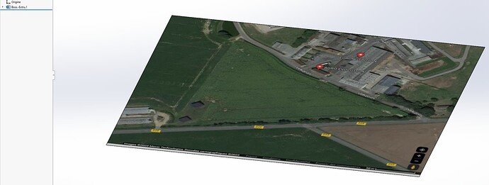
For the ground plan I glued an image on one side of a very simple part.
have a good afternoon
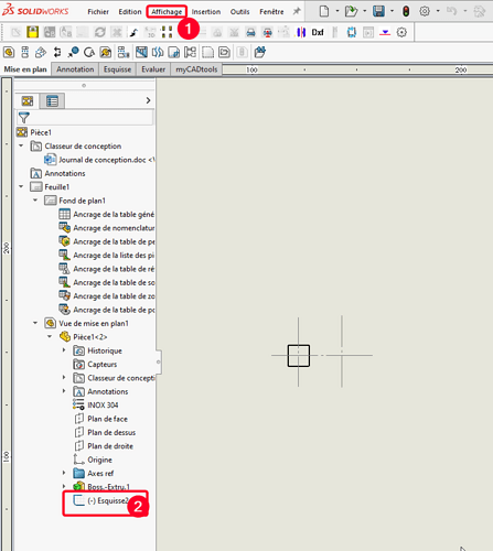
You insert your view(s) in your MEP and then in your tree and you display the sketch:
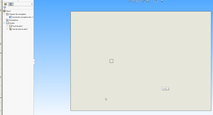
Before:
After:
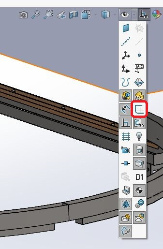
in 1: View, Hide/Show, Sketch
In 2 right click Show
1 Like
That's what I do, and on a fairly heavy assembly, it doesn't work...
Do a new MEP after making the sketch visible in your room to see if it comes from there.
1 Like
Indeed, it becomes visible from a new MEP.
On the other hand, it remains invisible in the assembly although it is ticked "make visible"
In the assembly, is the sketch display enabled:
2 Likes

