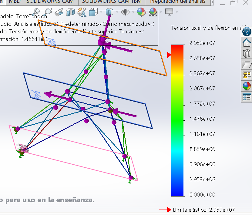
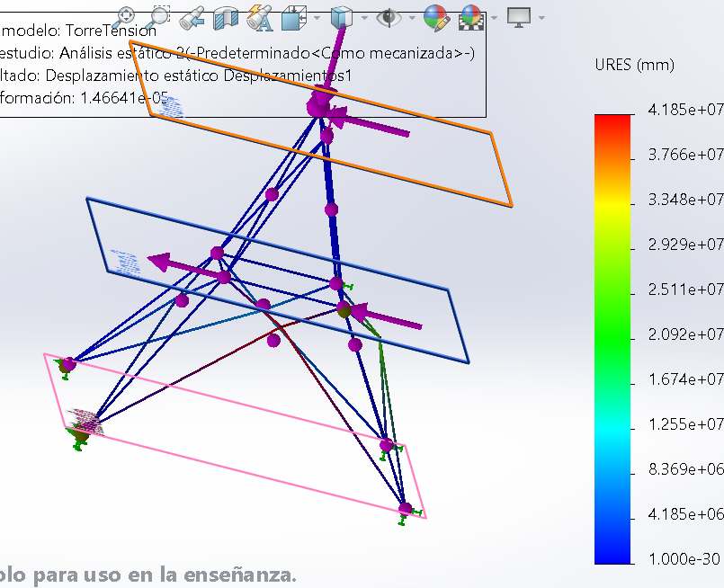
I am a senior Mechanical Engineering student currently diving into SolidWorks Simulation on my own. I have run into a frustrating roadblock with a structural analysis, and I would be incredibly grateful for any advice or pointers from the more experienced users here.
The Setup:
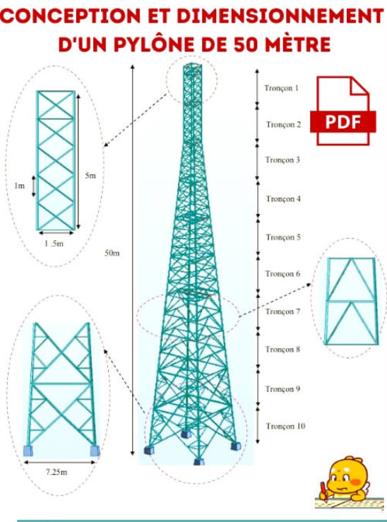
Model: 3D transmission tower created using a 3D sketch and Weldments (square tubing).
Study: Static Linear Analysis.
Elements: Configured primarily as Truss elements
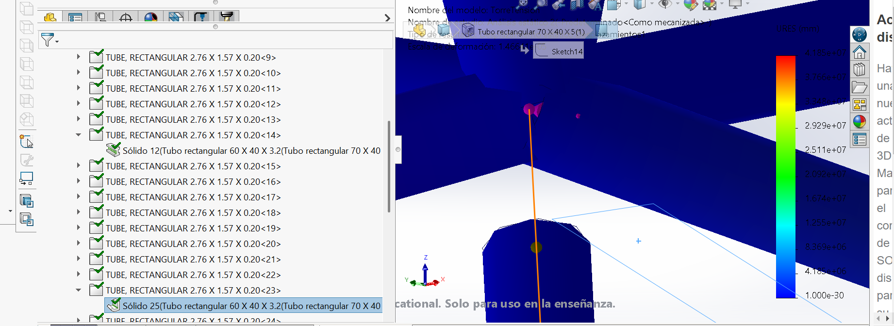
The Problem: At several intersections—especially where diagonals cross in an « X » or at the main frame corners—SolidWorks is failing to create a single, unified magenta (connected) joint. Instead, the so
De plus vos renforts en croix (4 tubes) tel-que vous les avez conçus ne reprennent pas les efforts correctement, ils sont fragilisés en leur centre.
Il faut hiérarchiser votre structure et vos renforts. un tube (diagonale), et deux tubes complétant la croix. Même là je pense que ce n’est pas le top.
N’hésitez pas a décaler la ceinture du premiere étage comme l’apui des renforts.
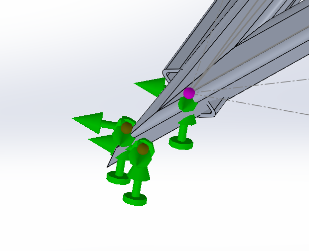
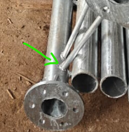
Comment sont fixés ou liaisonnés les pieds au sol?
Il faut parfois ajouter des noeud artificiellement. Exemple pour un « X » de renfort, 2 poutres ne suffisent pas! il en en faut 4 avec un noeud commun au centre.
Il s’agit d’un calcul de structure poutre, on fait donc l’impasse sur les raccords, ne t’encombre pas des ajustements de poutres.
En effet le point rose montre un noeud définieau centre du « X »
Il faudrait voir le modèle pour comprendre les efforts appliqués et les directions des déplacements.
Sur ce genre de structure, le maillage poutre semble logique mais avec la puissance de calcul des ordinateurs actuels, un maillage et calcul volumique bien que plus long évitera ce genre de souci de liaison dans les coins ce qui peut permettre au global de gagner du temps.
Si on fait du calcul de structure tubulaire à longueur de journée, ce n’est pas forcément vrai (mais on trouvera les solutions de maillage adaptées).
Il est également possible de faire du mixte : garder les coins soudés en volumique (ou seulement ceux qui posent problème) et les longueurs en poutre. Par contre cela va compliquer fortement la création modèle de calcul.