Hello
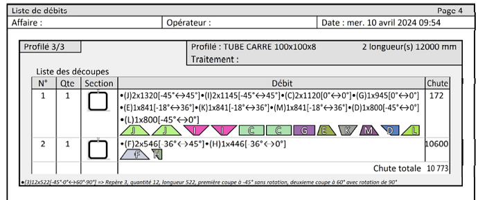
I encounter difficulties with the Cutting Optimization tool, I explain myself, I manage to integrate a project into the tool, it recognizes all the profiles and lengths of flows, I manage to set up my different beam lengths, and generate a report that is coherent, so far so good. However, when I look at the report in more detail, I realize that it can't " nest " the cuts at 45° but it puts them " side by side ", so for an optimization tool, it's not great...
Second point I can't manage the orientation of my profiles, the option remains greyed out all the time.
Thank you for your help
Sincerely, Kevin
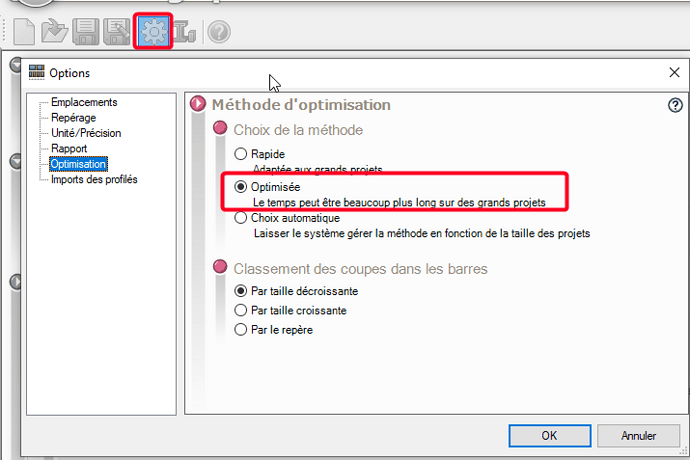
Did you choose the optimized mode correctly?
For orientation, it's automatic when importing Solidworks.
To use it, you have to add a manual flow (with the +)
Yes I even tried the 3 modes to see their differences but nothing changes...
I don't really know where to look.
Okay, it's noted for the orientation of the pieces.
Thank you in any case
I did an import with a lot of 45° cutting and yet it seems to fit together.
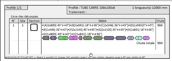
The total is nested:
What is your version of the MyCad utilities?
Can you save your CuttingOptimization project (.mcoo) and submit it for verification? (Just the tube concerned if possible)
I actually got a different result with my version (2022 SP2.1):
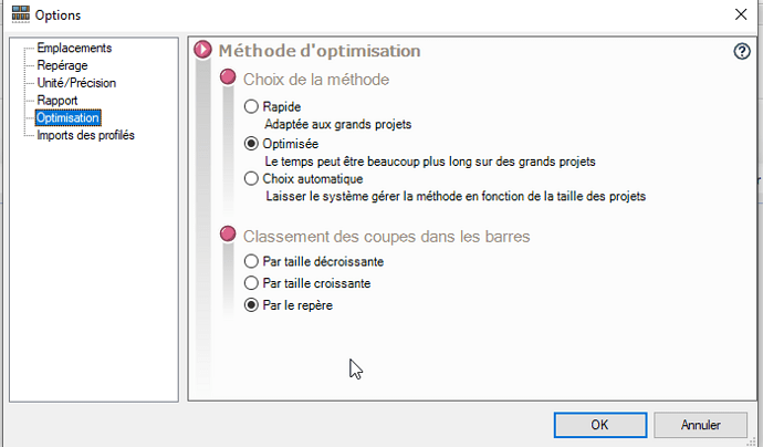
Blade width =0 and initial drop also and for optimization options:
Maybe someone like
@fmarchand (Visiativ) will be able to tell us why?
Edit:
Have you tried with this option:
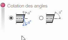
The 2nd bug it seems to me and doesn't accumulate the lengths as it should.
ah well okay it seems optimized !!
Yes I tried this option, it has no influence on the orientation of the cuts simply on the indication of the choice of angle for the operator.
I hadn't tried on this set, but indeed on this one it also bugs.
I had tested it on a more complex set and I had no bugs... strange!
I just tried it on another post, same version of SW, but with MyCAD 2024 SP1.2 I get exactly the same result.
1 Like
Hello;
In your examples (above) the difference seems to be in the choice of the classification of the cuts in the bars:
It is probably necessary to favor " By size..." rather than " Landmarks "
Kind regards.
I used the 3 different options
- By Descending Size
- By Increasing Size
- By the marker
no difference on the report using the same file...
the more I scratch in the tool the more I tell myself that he has a problem... when I change the settings nothing changes... even for the repair part I asked numerical instead of alphabetical it doesn't change ... The same goes for the choice of the optimization method or the choice of the classification of the cuts...
I am desperate...
Same with me,
The option change doesn't always seem to work in " dynamics ", I had to restart the utility several times (and re-import my mechanically welded at the same time) before noticing the changes.
I had also tried to restart the tool but it had no effect ... What a shame because the tool is really simple and could be great but here we are far from optimization.
This also means that they (Visiativ) have not changed anything on the 2024sp01 version of the mycadtools (this is the version installed here). So no need to update in your case.
Moreover, I find that the majority of their tools, although very practical or even essential for some, are less and less well thought out .
1 Like
I have two workstations available, so I had done the test with the latest version no change ... Too bad.
I fully share the point of view
Hello
Obviously it is a scan of the mechanically welded, in this case the orientation is not available since recovered from the 3D
As far as nesting is concerned, the cutting diagrams are there to represent the coordinate system on the bar, but it is not represented inverted (we are working on a more precise ratio in a future version) but the system has detected a cross-section symmetry (because square tube could not be on an angle for example) and it takes into account this possible nesting in the calculation
By the way, if we add up the cuts 2x1320+2x1145+2x1120+945+841+841+841+800+800 = 12238 (plus the cutting lines) i.e. > the raw length, we can see that it nests
As I said, the report only displays the sequence of diagrams of each section but does not orient them, we are working on it to improve the report.
5 Likes
Hello
In addition to @jfaradon's answer:
R&Dmy - Evolution #183197
Overall improvement in cross-section reporting and visualization
Kind regards
1 Like
