Hello, we have a question about the correct dimensioning to use in the drawing.
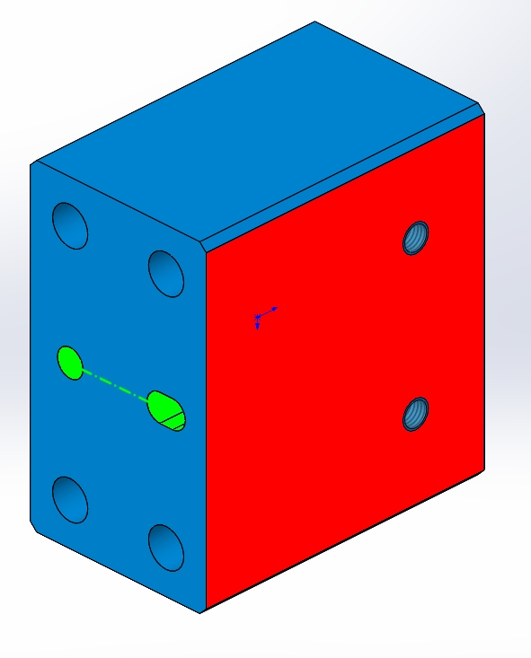
We had several parts for which we did not know how to quote, the latest one is a parallelepiped part which is put in position by a pin + a groove and then screwed (very classic so far, see in green below the pin housings). We need the red side below to be perpendicular to the virtual axis passing through the center of the two dwellings (green axis)
The only way to quote that we have found is to do as below
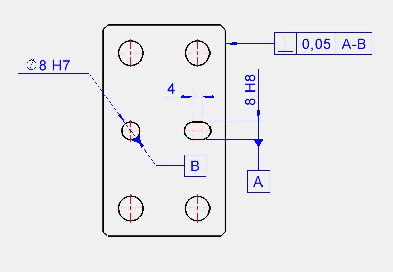
In this case it can work, but we would rather use the opposite logic, i.e. that the red side is a reference face and find a way to indicate that the axis passing through the center of the H7 and the center of the groove is perpendicular to the red face.
If you have any ideas, we're interested!
Enclosed is the document in question.
A+
Example.SLDPRT (141.8 KB)
Hello
I think I'd do something like that
1 Like
I don't have the dimensions (lazy to redraw it exactly) ... but otherwise, I even think I'd do it for your rating
You place your face in relation to your oblong and then a location of your Ø8H7 in relation to these two references.
So your H7 is placed in relation to your face AND your oblong
Hello
For me the red side would be your main reference A
Your oblong B is perpendicular to A
Your hole C is placed symmetrically with respect to the oblong B (the middle plane extracted from the 2 faces of the oblong)
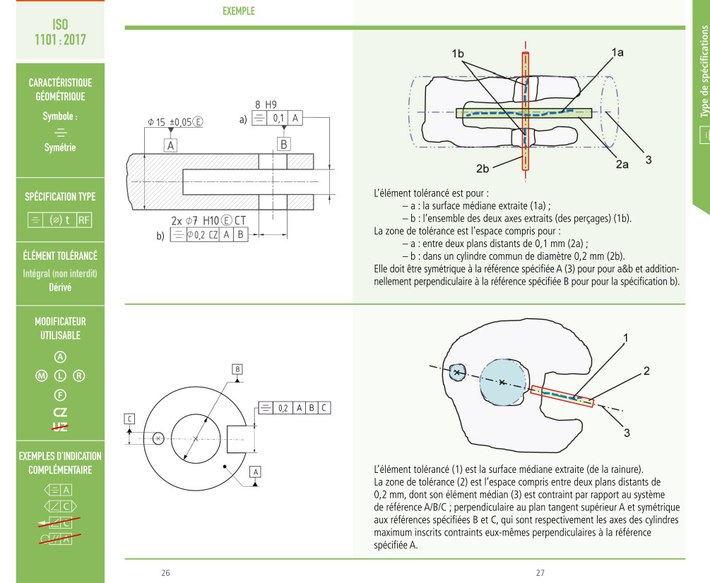
As a gift, an excerpt from the Cetim memento (Memento_ISO_2018_FR Tolerancing) for symmetry (similar problems but not with the same orders of importance as you):
2 Likes
Hello
I will see more of a quote of this type. Tolerance intervals to be reviewed according to the pins that are probably facing each other.
1 Like
So, if I can be fussy @Cyril_f ...
the symmetry of 8H7 is made with respect to an axis on Ø8H7. That is to say that the symmetry is made by an axis coming towards us on the screen => which seems to me to be complicated
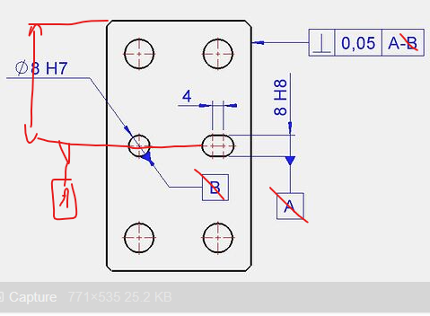
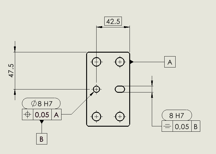
This is why I would rather put the reference B on the line of hill 47.5 pointing to the Ø8H7. Thus, you can keep the symmetry by plane B (and even, to be quite good, 47.5 should be framed slight_smile: )
2 Likes
Hello, thank you for your feedback. It is not easy to find a fair quote that remains easily understandable. In your @Cyril_f I have the impression that there should also be a perpendicularity on the groove, because if it is not perpendicular to the face it " drags " the 8H7 with it.
@froussel you're probably right it seems to me to be the simplest, on the other hand the perpendicularity tolerance will have to be very low because once the symmetry is projected up to Ø8H7 the perpendicularity gap can quickly be significant, especially if the groove is short.
@coin37coin I think it works but it bothers me a little to place a large face in relation to a small groove, in the spirit and in the realization it's rather the opposite that we will try to do.
Hello
It all depends on the standard, in the plans, there are specifications induced by the standards and among other things, via the global standard related to the industrial design.
Otherwise, replacing the symmetry with a localization of the faces will induce perpendicularity to the face.
2 Likes
@pierre-lou_buot , I agree with you relatively. A large face with a small groove is not crazy.
So, the remaining solution is to @Cyril_f where you locate your Ø8H7 in relation to this face AND you locate the centers of your oblong in relation to this face in order to orient the latter
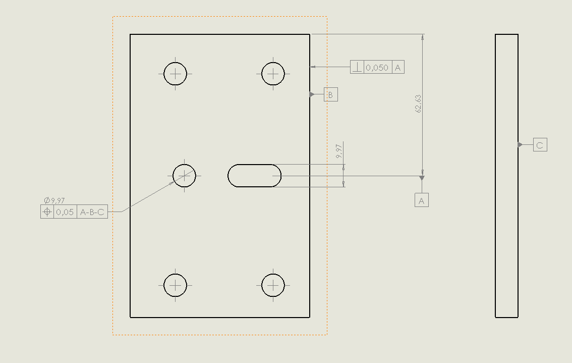
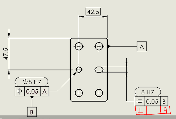
Yes @coin37coin a valid solution would be this one (logically with the perpendicularity above the symmetry):
I had roughly proposed the same but with the oblong in B instead of the smooth hole.
The choice of the final dimension will depend on the relative importance between these 2 references (smooth hole and slotted hole)
1 Like