Hello
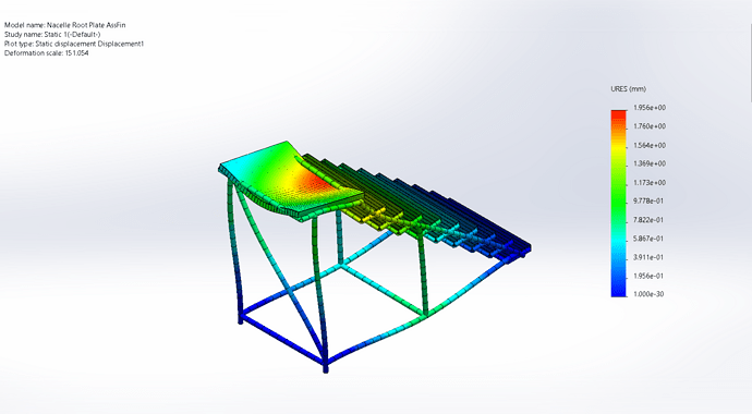
I have designed a nacelle, I have established a galvanized steel " floor " that rests on an S235 steel frame, the problem is that when I run the simulation with a force of 8000N on the floor, the displacements are not distributed in the chassis and I simply see the displacement and deformation of the floor floor. (See first photo)
The result I expect corresponds to a displacement and dissipation of the loads in the chassis.
1 Like
First of all, welcome to the forum where you will find many answers to the questions you have.
As I don't know your level of knowledge of SW don't be offended if we offer things that you know perfectly well or that are different from your practice.
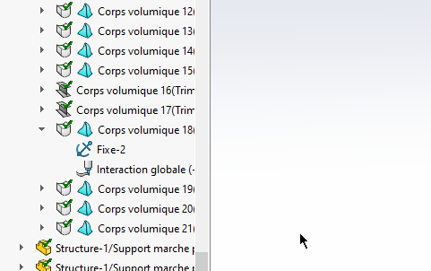
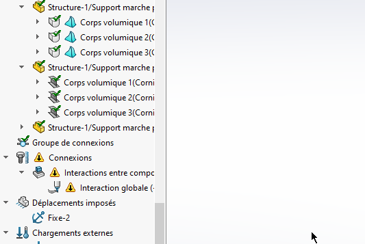
So by looking only at the image I see that you have chosen the beam mode. And I don't see how you treated the other elements that are not comparable to beams in everyday use. (The elements of the steps for example).
Personally I convert everything to volume mode
In your model you have interpenetrations which is not normal.
Also, we do not see where and how the efforts are applied.
To say more, you should post your ASM.
Do on the asm ==>File ==> Pack and go ==> select ZIP file.
Which version of SW do you use?
Kind regards
4 Likes
Thank you for your answers, for information I work under SLDW 2021.
For the design I chose 60x40x3 and 40x40x3 profiles, all in S235.
Here is the 3D of the model.
Nacelle.rar (4.9 MB)
Thank you in advance for your help.
Hello
I'm under 2020 so I couldn't help you directly.
On the other hand, the image shows that the contact between the shell of the floor and the beam on the side of the staircase is not well taken into account by the software (while it seems correct for the other 3 sides).
This point therefore needs to be reworked.
Otherwise I'm like @Zozo_mp : I work in volume, it's easier to model and not necessarily much longer with modern PCs.
There is a good chance that the contact will be correct if you switch to volume.
1 Like
@naehu.beaubois
The problem comes from the design of the nacelle 2 grid.
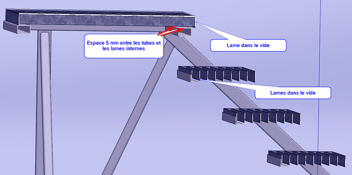
Indeed, the "Blade 1 nacelle 995 <2> is in the void as shown in the cross-sectional view.
I find it curious that
1°) all the effort be transferred to the 3 blades (the fourth is in a vacuum)
2°) that the blades 1 Grille Nacelle 796<2> and following are not in contact with the frame (there is 5mm of void. As a result, the entire basket will deform until the blades 1 come into contact with the frame.
Note that although it is not visible on the simulation, you have the same problem with stair treads. This is not too noticeable because they do not have a direct charge.
Otherwise, from the point of view of the results parameter, in my opinion, there are some points that can be improved.
In Von results set by default SW gives distortions of 300 or more You have to go to settings and check either real or put the number you want for example 5 times OR ten times.
You will see when the simulation becomes almost normal again.
Optimized simulation is underway
Kind regards
PS: I'm making a totally off-topic remark. (forgive me)
I think that if you have 800 kg on the platform, you have to count that the CG of this mass will not be at ground level but much higher, which will increase the potential spill.
In addition, nothing prohibits two people weighing 95 kg from being on the steps at the same time.
Personally I wouldn't have fixed the steps this way for practically the same reasons as the platform.
If our mechanically welded specialists pass by on their way back from the beach or the mountains, you may make some additional observations.


1 Like
Good evening
Final clarifications and remarks
The title is nacelle, I deduce that it is either mobile or fixed, i.e. anchored in the ground.
1°) if the four legs are anchored solidly in the ground then although the plates of the legs are a bit tiny, your simulation is correct modulo the other remarks already made
2°) If your basket is on wheels then you cannot put that the four legs are fixed in the imposed movements. You must put at least two feet on a flat support.
This then gives the attached video.
That's the main thing to discuss of course
4 Likes
Hello
Thank you for all your answers, I will try to apply this as soon as possible.
To add some information, the nacelle already exists, I took the dimensions of the chassis to apply them on the model. Like you, I found it very surprising that the grates of the gondola are "in a vacuum" and that it only holds on 3 sides. However, this is what it corresponds to. The fixing of the steps with the 30x30x2.5 angles.
Concerning the load of 800 kg this is also normal, the operator will assemble parts that can sometimes be close to 15 kg and this on several occasions, the basket can therefore quickly find itself with a load of 300-400 kg, so I preferred to put a coef 2 on the load to guarantee the rigidity of the whole.
All odds correspond to reality.
The basket is indeed on wheels. I will try to apply your advice, especially for the carrycot so that it can stand on all 4 edges.
1 Like
Hello @naehu.beaubois
As for the safety factor, I don't know what our colleagues think, but personally I don't put the security coefficient before the first simulation.
On the other hand, I am uncompromising on all the weight elements that will be placed on the frame and also on the Center of Mass of each component.
You should not hesitate to put loads at a distance, which is more realistic than putting the load at ground level for everything. Obviously I put one for several remote charges.
cf. my remark on people who can stand at the same time on the steps.
I use a value that is worth what it is worth.
For each step I put 95 kg of weight of a person.
As there are almost always several steps, I repeat the load of 95 kg and spacing them 60 cm apart. For the platforms, I gain 500 kg per m², which corresponds to the standards of a system receiving the public.
The size of a person in the top view is in a square of 60 by 60.
This is also used for the footprint on the platform where there is a mixed Parts + staff.
I prefer to work this way because it avoids oversizing the parts.
For the Solidworks security coeff gives it in the results (if it is not enough, you sample your frame again only on the weakest parts.) The advantage of the coeff secuted by the simulation is that it tells you exactly in visual where the coeff is a little light.
We can do a design dissection to refine where the internal forces of the material are.
The other results give only the external aspect.
Kind regards


