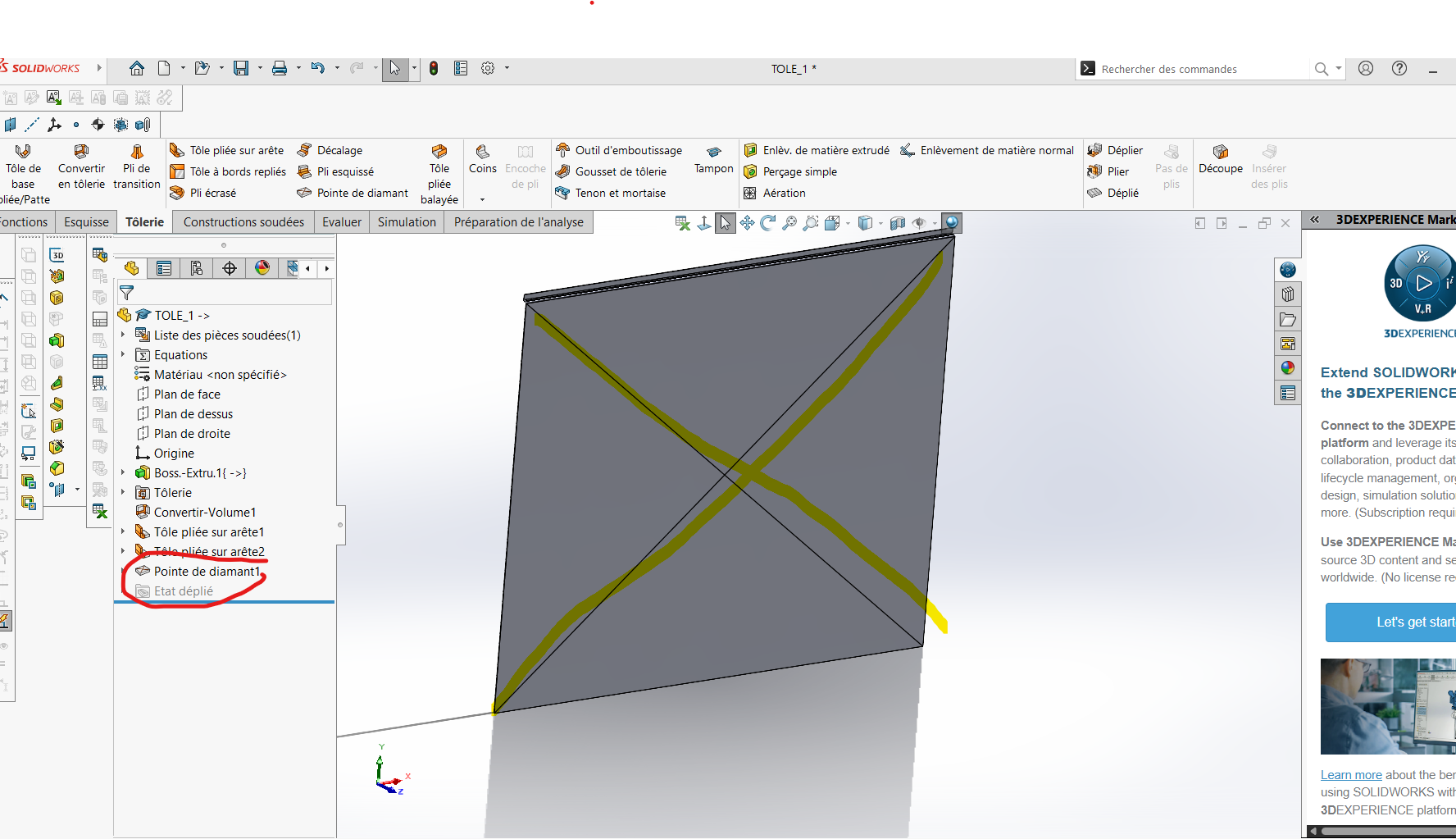
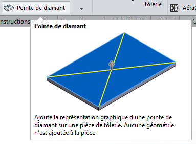
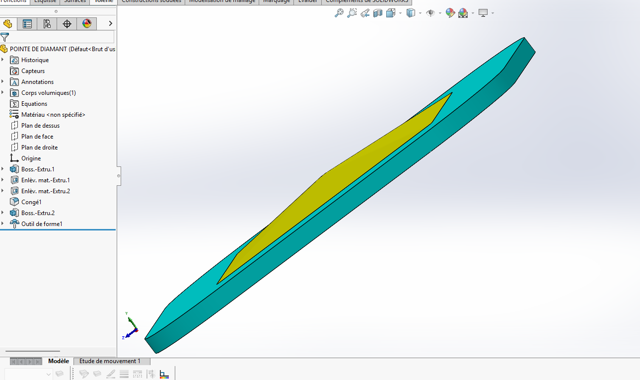
The diamond tip function is purely graphic, as its description indicates.
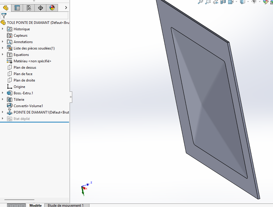
Personally I model a pyramid and I convert it into sheet metal, for a drawing it's practical. But there will always be an edge of the pyramid that is not connected.
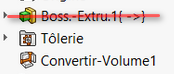
I advise starting from a sheet metal function rather than a conversion of an extrusion. Secondly, I am in favour of a real modelling of the " diamond " (as suggested by @arthur.fonmarty). I also recommend avoiding keeping your external references (as much as possible): (depending on your Solidworks settings, this may cause problems with updates to your components).
I don't understand why you say that in the latest version we don't need a tool? in Solidworks 2026 SP1 (standard license), the diamond tip function only makes the lines and no 3D distortion
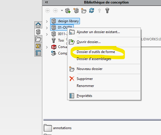
Starting with SW2024, it is possible to use the Stamp tool to create sketch-based parametric shape tools to be applied to sheet metal parts. In previous versions, sketches and functions had to be saved as a " shape tool" part (. SLDFTP) before it can be applied to a sheet metal.
Not sure of the real interest of deforming the sheet metal, for me the representation is more than enough for a large majority of cases. The representation on the 3D model and the MEP is enough to perform the function by a bending machine and for the 3D visual, as well as an exact development of the sheet metal (very minor deformation because of the very low angle) and in my opinion this is the whole point of the thing.
@Silver_Surfer It must also be indicated in the file that he is: " Shape tool file" (a detail that made me c...)
@sbadenis the advantage of doing with the right tools is that there is often less function, and it's less cumbersome. As far as graphic representations are concerned, I agree with the idea of the simplicity of a representation. But seeing how bored I am to represent threads for a screw or a thread on SW. I save time by making it for a minimum of resource. But it's a choice