Hello
On a drilling table we have the X and Y positions, but is it possible to have the Z positions when the holes are not on the same face.
Because when creating the table you click on the different faces and it works fine, but then you lose the information about the difference in height between the faces.
Thank you for your answers
Fred
1 Like
Hello Fred,
What do you mean in the " Z " position?.
Here's what I can do with a table SW2022SP4.=>

Good luck, @+.
AR.
Hello A_R,
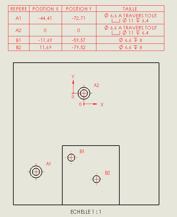
as you can see in the example below, the table shows me the positions in X and Y but not in Z. For me the Z is the position in depth, for the example below the holes B1 & B2. In fact it is to have the information that A1 & A2 are not on the same face as B1 & B2.
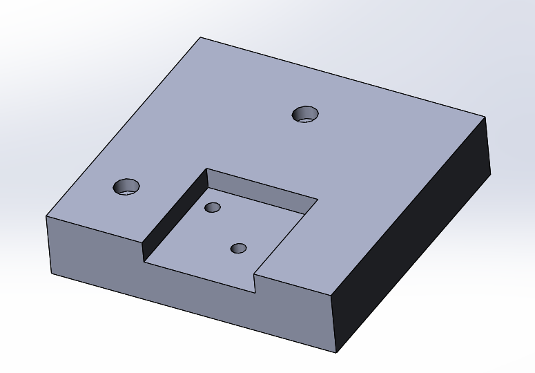
In fact I don't see that I have two surfaces:
surface on which there are countersinks
surface on which there are the holes Ø6,6
In summary, I would like to know that my holes are not on the same side.
Fred
1 Like
Sorry @fred but the drill table only includes 2D (X and Y), it does not have the Z-axis option.
And I don't think there are any requests for changes from Solidworks in this direction...
https://help.solidworks.com/2020/french/SolidWorks/sldworks/t_create_hole_table.htm?id=7d9c75cb1f9845c3a8ac5352d17c4cde#Pg0
1 Like
Hello @Maclane ,
Too bad there isn't a way to inform that the holes are not on the same surface!
2 Likes
It is always possible to identify faces with marks and add them to a new column in the drilling table... but it's semi-manual => Waste of time and problems with updates...
2 Likes
Yes Fred,
Indeed there I understand better.
For the moment I don't have a solution, except by going through an offset cut, or others. To dig into ...
Well, as Maclane says, "it's not possible".
@+.
AR.
1 Like
Hello
Why not add views?
Front view + side view + isometric view
1 Like
You have to make 1 drilling table per surface. This will be clearer for machinists, especially with the drilling and tapping depth information, as these have the leading face as a reference.
This will also be clearer for the person in charge of costing the file.
1 Like
Hello @Le_Bidule ,
Totally agree with you, but you have to rework the second table to modify the " start at: " markings and indicate the offset of the faces. But your proposal is a solution.
Fred
2 Likes
A plan is a communication tool. In our business, this is technical information, it must be clear and address the entire chain of interested parties.
In this case, it will obviously be necessary to use dimension views to define the geometry of the part.
A drilling table has 2 functions. Lighten the views in the number of dimensions. Fill in the coordinates of the drill axes to the machinist when programming the NC.
3 Likes