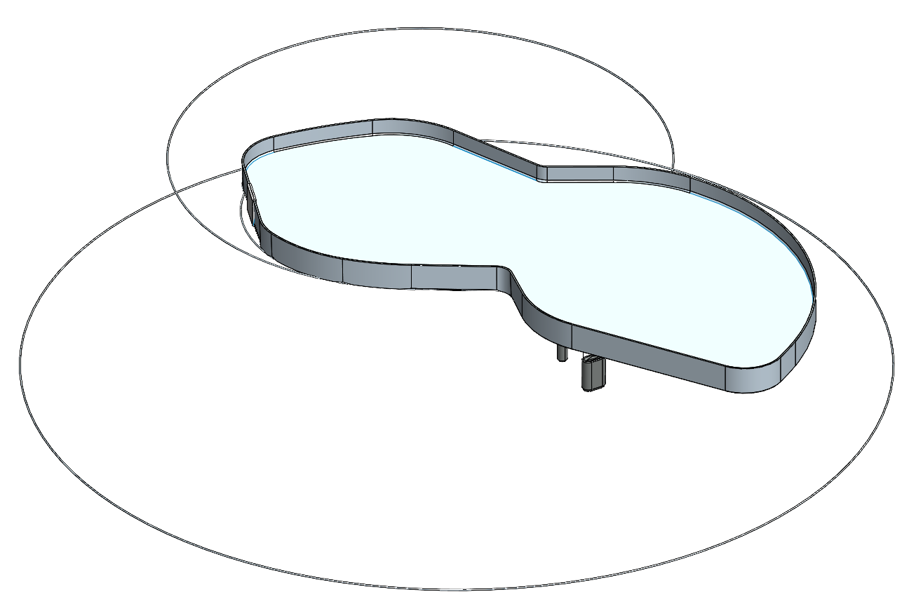
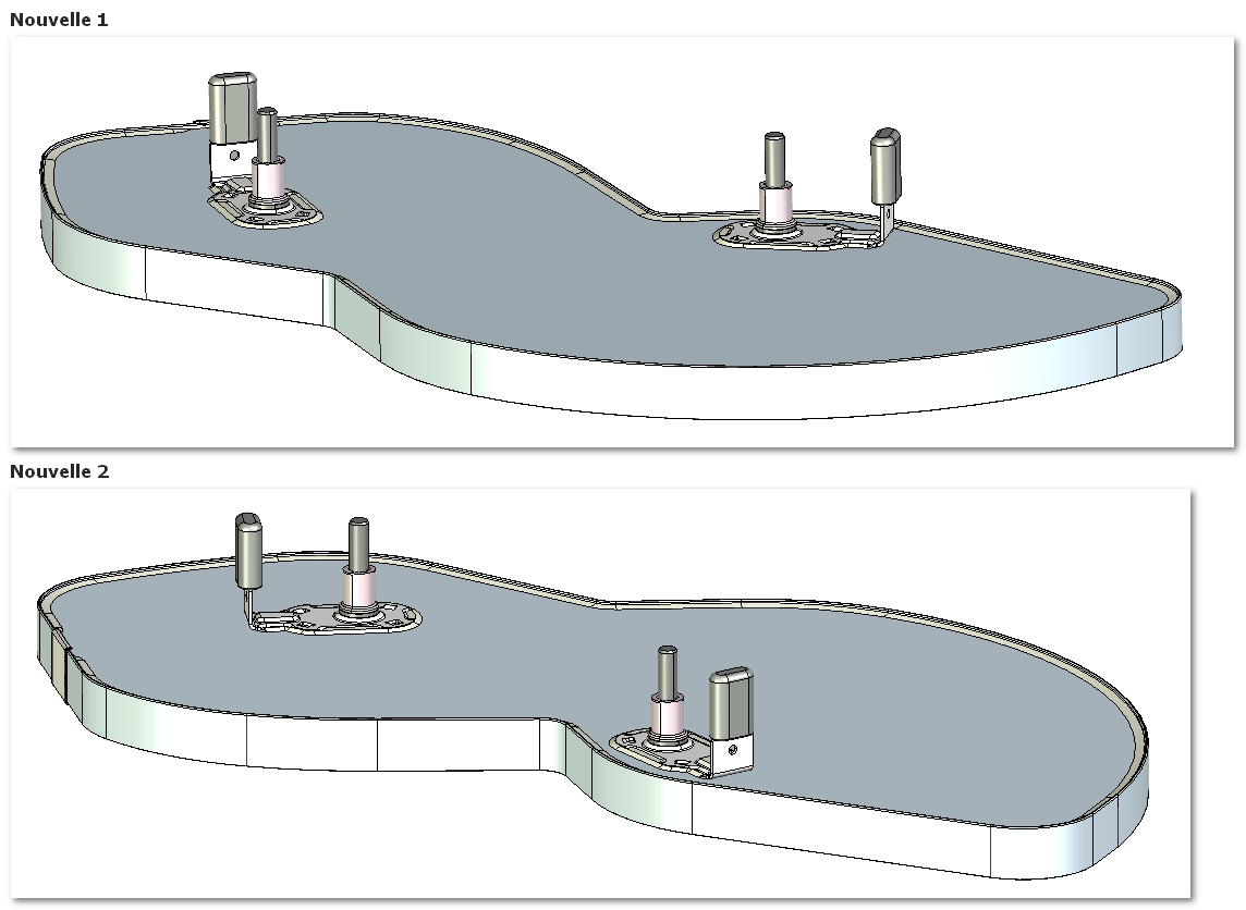
I received a STEP file of a tray from an assembly. When I import it into SolidWorks and then save it as a part, circles (similar to revolutions) appear at different points in the model.
The person who sent me the 3D doesn't understand where it comes from either, and on my side I haven't found any solution to delete them.
Do you have any idea of the cause or a method to correct this problem?
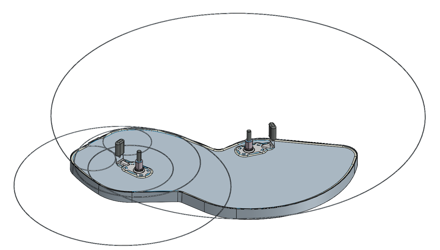
Since the file is from a STEP, I don't have access to the sketches. Looking at the tree structure, I see that the circles are linked to the entire top, except for the hardware visible underneath.
I tried to create an extrusion to remove them, but SolidWorks doesn't recognize these shapes as true thickness, so the operation fails.
Would it be possible to share this file so that it can be tested? What is its original format? Do you get the same result with a Parasolid (*.x_t) or *.iges file?
Hello 3 possible cases, either the manufacture of the step is not good, or the import configuration of the step is not good, or both There are a plethora of topics on the forum concerning step (import or export)
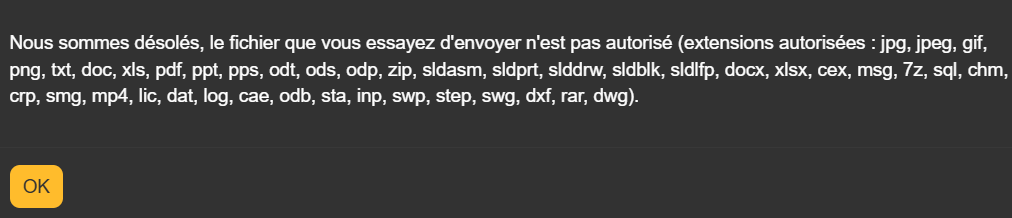
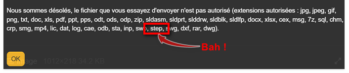
Of course, which platform do you want me to go through? Because I can't share a step here. Unfortunately I don't have the possibility to have the information of the original software
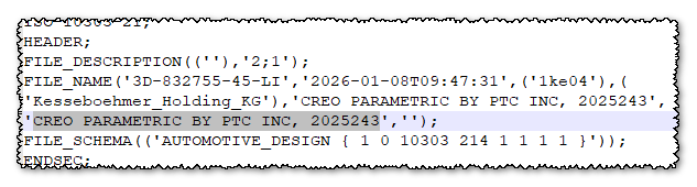
Technically they are the same formats... For your information, when you have a file like Step or IGES (or anything that can be neutral 3D), by editing the file with a text editor (notepad, or better notepad++), it is often possible to see the original format: here: CREO PARAMETRIC BY PTC INC, 2025243
Opening with SW2022 SP4.0 => Without 3D interconnect !! No worries either, on the other hand many, many surface discontinuities... Here are their Parasolid equivalents to test at the opening. plateau_2026-02-02_1520.zip (2.5 MB)
The person who sent me the 3D doesn't understand where it comes from either, and on my side I haven't found any solution to delete them.
Why not ask him for the file again in an export format more suitable for solidworks (parasolid .x_t for example) The step format is a neutral format but it degrades the files a lot and is very heavy. If you have 1000 components in your assembly during an export it will create 1000 different bodies during the import unlike the x_t format which will create 1 and repeat it 1000 times. Edit: I would add that parasolid is the graphics engine of Sw (and also topsolid and solidedge) so no degradation when exporting one of these softwares.