Hello everyone.
I'm calling on your technical knowledge because I'm drying up a bit even if I have a little idea.
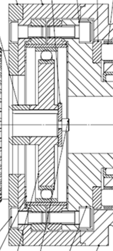
Can someone tell me which mechanical component is represented in the center of the image? Planetary gearbox, clutch...
Thank you for your answers.
Hello @OlivierH
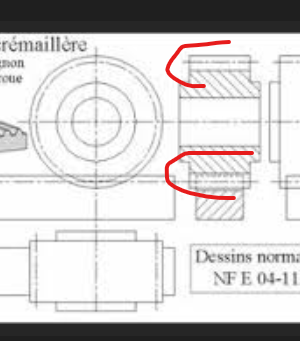
It's not a gear it seems to me, the teeth of a pinion are not represented like that in industrial drawing.
But as below
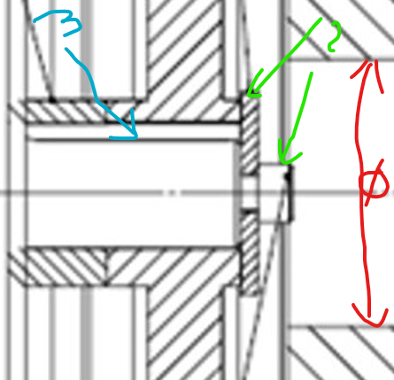
This system allows the central piece 1 to rotate (one rotation) and the ball 2, allows the elements on the outside 3 to move laterally, or to have freedom laterally.
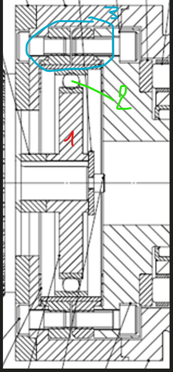
Much like a gearbox dog, can turn and move sideways to mate to a one-speed sprocket.
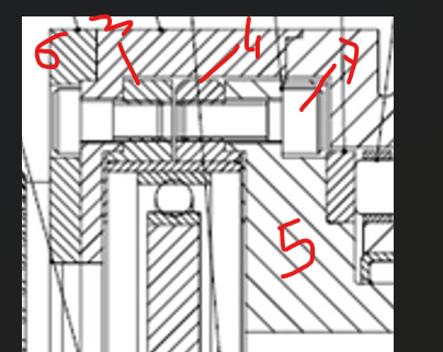
Part 3 is connected to 6 by a screw and serves as a stop surely, parts 4 & 5 are connected by screw 7 and can move it seems to me.
In addition, we can imagine that on the central part the bore 1 serves as a clearance for the washer and the screw 2 when the assembly moves, or its disassembly?
3 is a key that allows rotation drive
Do you have the drawing as a whole?
3 Likes
Hello,
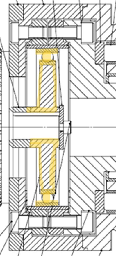
I will see this set in yellow more as a silent block (peripheral circular part would be made of rubber). But indeed @FRED78 if we could have the entire plan with the nomenclature it would facilitate interpretation
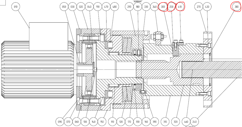
Thank you for your answers. Here is the complete plan but I don't have the nomenclature. It is a clamp.
Hello @OlivierH ,
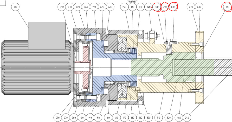
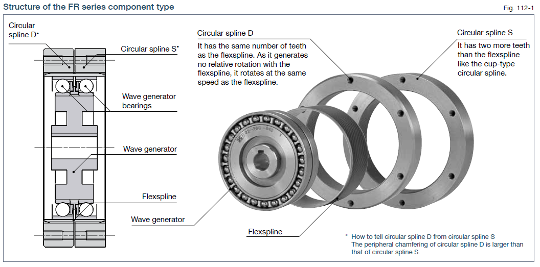
Between the 060 drive unit (in pink) and the 140 nut (in blue), there must be a low-ratio speed reducer. The representation is mediocre, but the overall appearance is reminiscent of a Harmonic Drive FR series gearbox.
2 Likes
Thank you very much @m_blt .
I hadn't thought of this kind of reducer.
You take a thorn out of my side.
Thank you again. ![]()
@m_blt
On the other hand, the 150 room is such fixed? Because the spring washers are not used for its damping?
For me the elements in yellow are fixed ![]() , or I take the problem backwards
, or I take the problem backwards ![]()
@Le_Bidule
I think it's a drive system with gear teeth with balls interspersed. It seems to me, I had already seen this system but I don't know what they are used for, for games or to take over the vertical load?

2 Likes
Congratulations @m_blt for the look and knowledge of this kind of product (I had never heard of this kind of high ratio gearbox until now)
For those who are like me (and who don't know cycloidal reducers either), a magnificent video of testing 3D printed versions by an Indian (with an accent understandable for us poor French):

4 Likes