Hello,
I am looking to position 2 verrins to respond, given their stroke and length characteristic, to 2 positioning of angles.
How to identify their hanging positions?
Thank you
Hello and welcome David_PIREL,
A small screenshot would be nice with your version of solidworks would be nice.
Thank you.
@+.
AR
Here is an example of a kinematic:
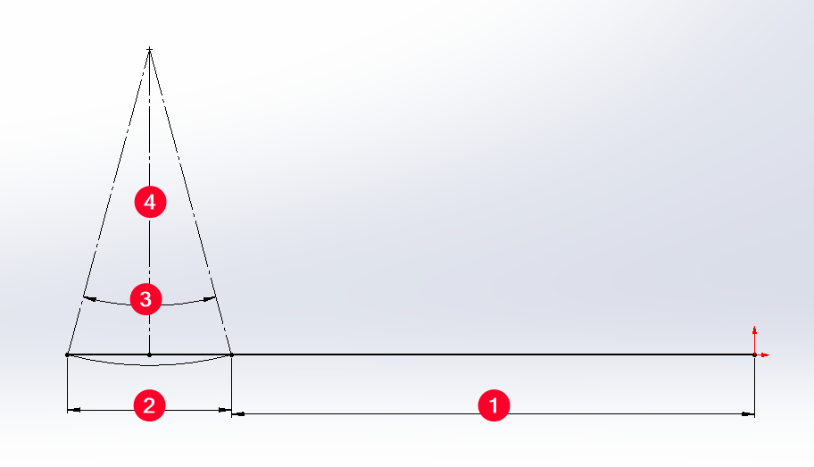
In 1 the axle distance of the cylinder clevis and the cylinder shaft was of cylinder in 2 the stroke of the cylinder.
In 3 your rotation angle.
In 4 the distance axis rotation of your system/cylinder.
You can choose to modify your cylinder stroke or your distance as needed (2 or 4).
It's not the universal kinematics but it's the easiest to test quickly.
@A_R about Autocad!
1 Like
Hello @David_PIREL ,
The two positions of the lever (in red), i.e. the points A, B1 and B2, as well as the two lengths of the cylinder, L1 (in green) and L2 (in blue), are known.
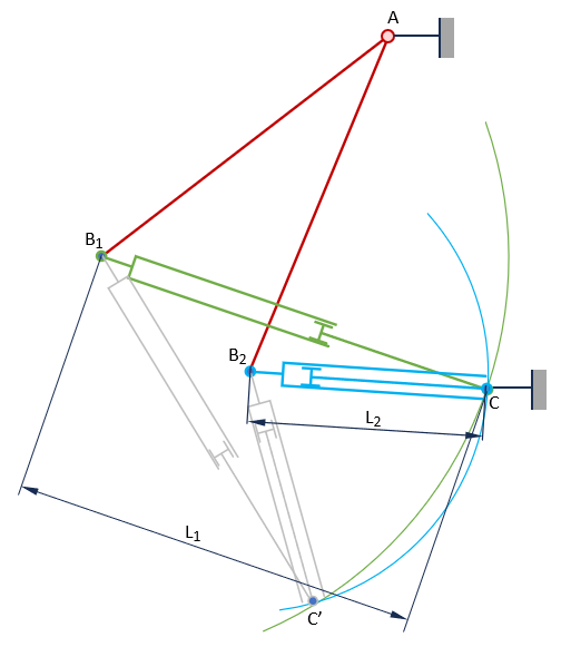
It is sufficient to draw two circles, with a centre of B1 and radius L1 and a centre of B2 and radius L2, to obtain in principle two intersections C and C' which correspond to the two possibilities of positioning the fixed point of the cylinder.
All that remains is to choose the most suitable solution: size, minimization of effort, etc.
If there is no intersection, it means that the cylinder does not have sufficient travel.
A sketch of Solidworks will give the result in a few clicks.
3 Likes