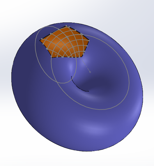
Bonjour, j’ai un petit casse tête à vous proposer, et sa résolution m’aiderais beaucoup pour mes futurs projets.
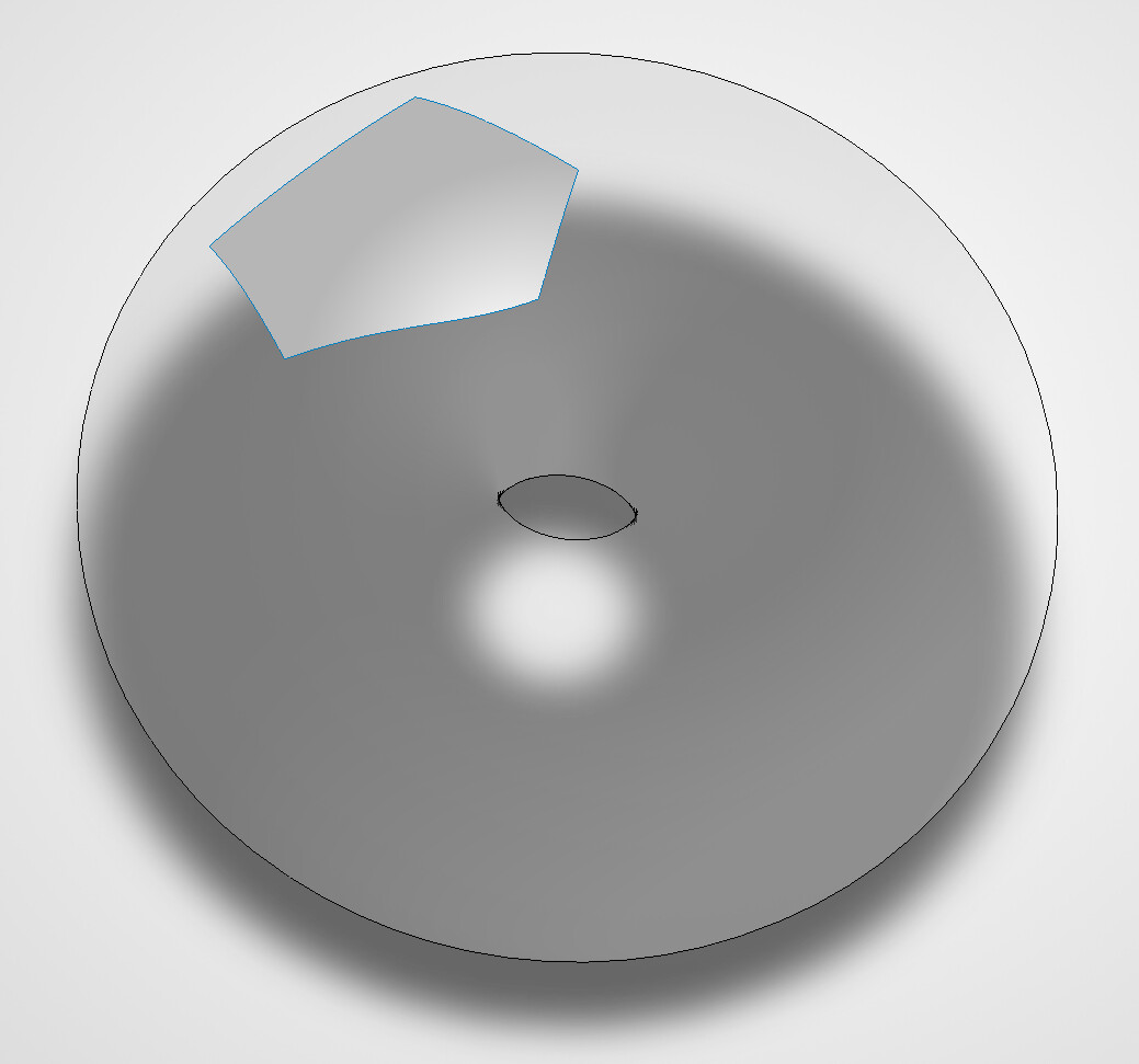
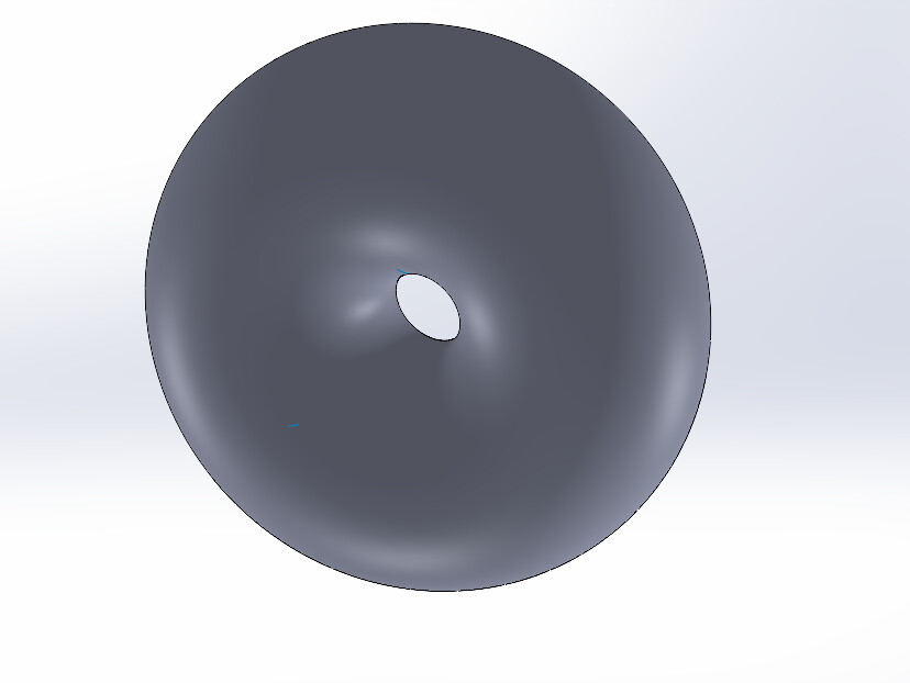
Question: Quelle serait votre approche si vous deviez recréer/récupérer ce torus en ayant comme seule référence une portion de sa surface ? (On suppose que le volume n’est pas aligné sur les plans d’origine)
Eh bien bravo et merci! J’avais la même intuition que vous sur l’entrecroisement des surfaces, ce qui fait que je n’avais jamais essayé de pousser la fonction jusqu’à récupérer la géométrie entière, mais il faut croire que la fonction est plus robuste que je ne le pensais.
J’ai une autre question qui en découle : La fonction nous redonne la géométrie complète du volume mais sous la forme d’une surface. La fonction « coudre » avec l’option « créer un volume » ne fonctionne apparemment pas sur une surface seule. Sommes nous donc obligé, pour récupérer le corps volumique de notre torus, de passer par un volume englobant puis de le découper grâce à la surface ainsi créée?
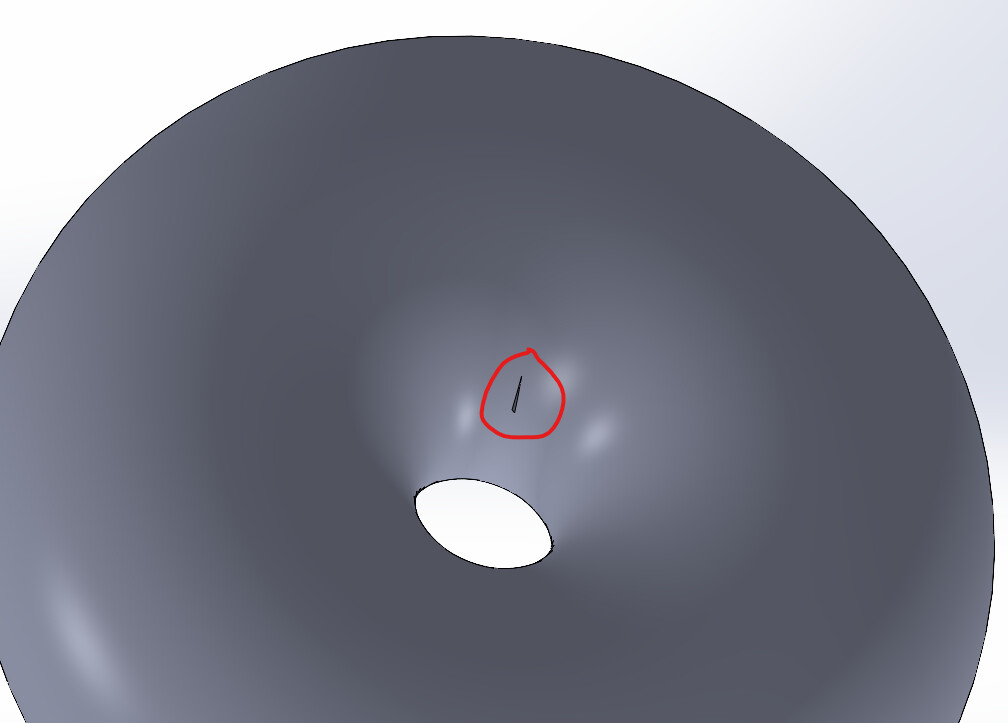
Même en rebouchant le trou, la fonction « Surface Cousue » nous affiche ce message :
NB: Je viens de trouver la solution en écrivant ce message, il faut utiliser la fonction « Epaissir » avec l’option « Créer un solide à partir du volume clos »
J’y suis arrivé bon après je ne sais pas ce que vous souhaitez en faire.
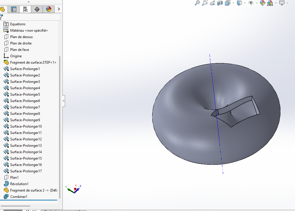
Avec le fragment j’ai créé une épaisseur.
A partir de la forme reconstruite j’ai créé un profil et créé une révolution.
J’ai inséré le fragment dans ma forme principale que j’ai ensuite soustrait (les corps)
Je propose une construction géométrique utilisable même dans l’hypothèse où le fragment de surface n’est pas rigoureusement une portion de tore (surface importée par exemple).
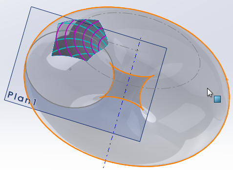
Le but est de construire un tore approchant le fragment, en retrouvant la section et l’axe…
Etape 1
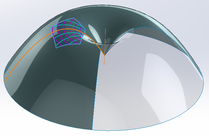
Sélectionner [Outils] > [Outils d’esquisse] > [Courbes de face].
Sélectionner le fragment de surface, et définir les nombres de courbes souhaitées.
Les courbes obtenues sont des splines au sein d’esquisses 3D…
Certaines sont parallèles entre elles (en rose), les autre sont convergentes et constituent les sections du futur tore (en turquoise).
Etape 2
Ouvrir l’esquisse 3D de l’une des esquisses « Parallèles » (la plus longue…).
Insérer un point d’esquisse (point P) à l’intersection avec l’une des esquisse « Sections » (la plus longue…).
Sortir de l’esquisse.
Etape 3
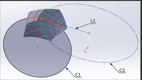
Ouvrir une nouvelle esquisse 3D (Esquisse3D0) et tracer :
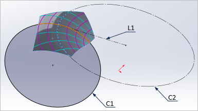
un premier cercle C1 passant par les points A, P et B,
un second cercle C2 passant par les points M, P et N
une ligne de construction L1 joignant Le point P au centre du cercle C2.
Sortir de l’esquisse
Etape 4
Créer un plan passant par les points A, P et B (Plan1).
Ouvrir une esquisse 2D dans ce plan, destinée à la génération du tore, et tracer :
un cercle coradial au cercle C1. Il s’agit de la section du tore ;
une ligne de construction perpendiculaire à la ligne L1 de l’esquisse 3D, et passant par le centre de C2. Il s’agit de l’axe du tore.
Etape 5
Il reste à générer le tore par révolution…
Bien vu , j’ai pensé pareil, mais je ne savais pas par quelle fonction passée.
Ma solution fait gadget à coté de la votre, mais les deux on le mérite de fonctionner sur le cas présent.
@FRED78 ,merci du compliment…
Deux remarques :
On peut réduire un peu l’arbre de construction en plaçant les « Courbes de face » dans une seule esquisse 3D, sous réserve de l’éditer avant d’appliquer la fonction.
Le principal intérêt de la méthode, c’est d’aboutir à une géométrie native de Solidworks basée sur une esquisse pour générer le volume final.
Il doit être possible d’étendre le principe à l’approximation d’autres surfaces.
Même fragment de départ, mais avec un arc de parabole au lieu d’un cercle pour approximer la section : le tore prend cette forme…
Tout dépend de l’estimation que l’on fait de la nature géométrique du fragment et de ses courbes de face. C’est là qu’étendre la surface du fragment peut se révéler utile.
@m_blt T’inquiete j’en ai en stock au vu de mon environnement pro
Je pensais aussi possible de prendre des raccourcis, mais je voulais suivre votre méthode jusqu’au bout.
Mais attention, simplifier un arbre c’est bien. Mais il faut vérifier le poids d’une pièce, et les temps de reconstruction. Car certaines fonctions sont gourmandes en ressource. Faite moi parvenir cette nouvelle pièce par curiosité
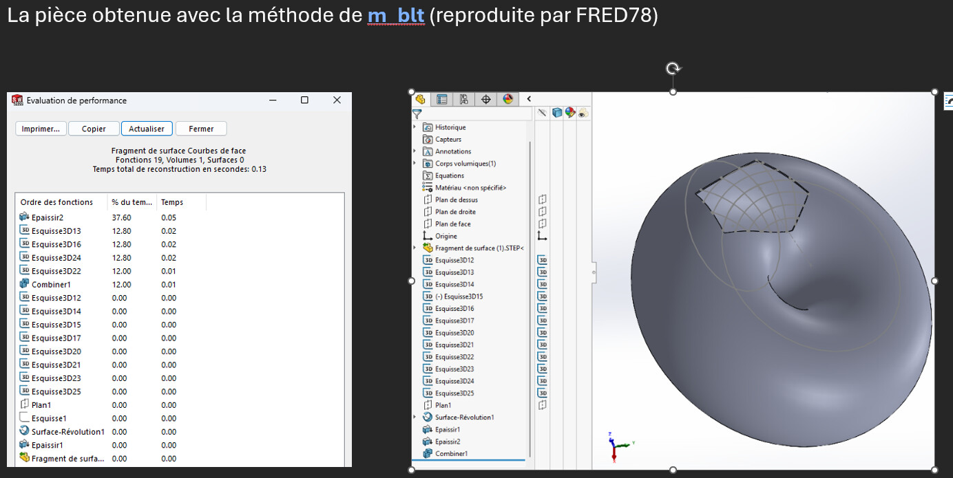
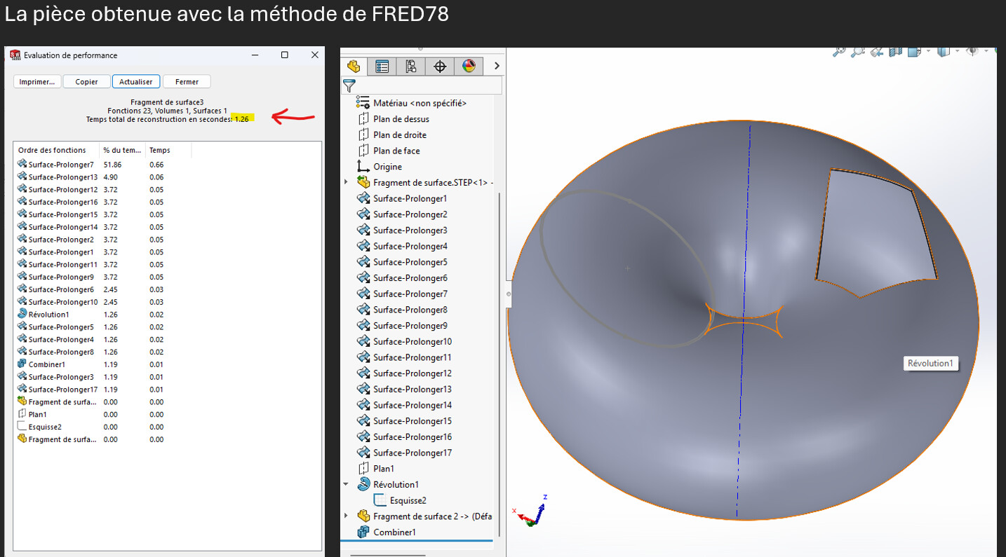
Petite comparaison entre les méthodes proposè
La méthode que je propose avec le prolongement des surfaces n’est pas si performante. Votre méthode @m_blt est sans commune mesure avec la mienne.
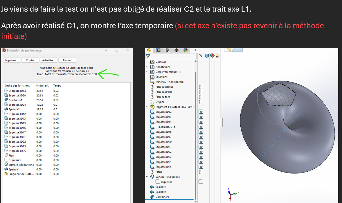
En optimisant la méthode de @m_blt nous pouvons encore améliorer les performances de la pièce : En supprimant le cercle C2 le trait L1, en utilisant l’axe temporaire de la pièce d’origine.
En fait, si on connait la nature géométrique de la surface, il est possible de retrouver analytiquement la forme de base en utilisant, selon le cas, 4, 5 ou 6 points particuliers du fragment de surface.
Le problème plus général est de disposer d’un fragment sans connaitre la nature de la surface de base : tore, cylindre, paraboloïde, ellipsoïde…
Dans ce cas de figure, ce sont les courbes de face qui peuvent renseigner, en plus de l’intuition de l’utilisateur.
Ce qui n’est possible que si le fragment est assez grand pour contenir suffisamment d’informations.
Il reste ensuite à évaluer les courbes de face du fragment. En plus de leurs formes, le fait d’en tracer plusieurs peut aider :
plusieurs arcs de cercles coaxiaux ==> forme de révolution, et son axe;
plusieurs segments de droites parallèles ==> cylindre;
convergence des courbes en un point ==> sommet sur la surface;
…
Enfin, il convient de tracer une courbe de la section aussi proche que possible de la courbe de face sélectionnée, avec un critère de qualité, mathématique ou humain : l’œil.
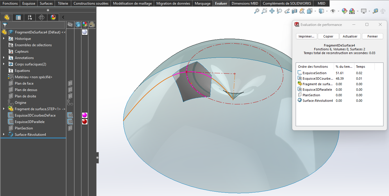
Ci-dessous, l’exemple basé sur le fragment proposé par @Léo_SABATIER , en supposant que les courbes de face sont des paraboles et non des cercles…
SW 2022 : FragmentDeSurface4.SLDPRT (146,8 Ko)
Arbre de construction compact, avec une esquisse des courbes de face ne comportant qu’une courbe pour chaque direction (case à cocher « Position » de la fonction).
Qu’il est possible de réduire encore en regroupant les esquisses Esquisse3DCourbesDeFace et Esquisse3DParallele en une seule.


 , j’ai pensé pareil, mais je ne savais pas par quelle fonction passée.