Bonjour les amis,
J’aimerais dessiner une hélice d’avion et pour ça je comptais partir d’un profil (esquisse) que je répéterais sur différents plans à des angles et des tailles différentes.
Auriez-vous un lien ou les grandes lignes pour arriver à ça?
Bonjour et bienvenue;
Dans un autre contexte, je conseillerai les configurations et les familles de pièces (voir aussi l’usage de Configuration publisher) mais les hélices d’avion sont complexes à modéliser alors leur ajouter de la cotation configurable dépendra beaucoup de votre niveau en modélisation 3D.
1 « J'aime »
Merci Maclane,
Je vais consulter tout ça.
Je ne suis pas un débutant (SolidWorks 2006) et pas un expert non plus.
Pour le moment, j’ai mon profil Naca paramétrable par équations, les différents plans de section à une certaine distance de l’axe de rotation de l’hélice.
Dans un programme je calcule toutes les cotes des profils et leur angle que je sauvegarde dans un fichier texte pour les équations SDW.
Pour éviter de recopier le profil de base sur chaque plan et d’ajouter des équations pour chaque point j’espérais pouvoir faire de mon profil de base des copies réduites selon la position et l’angle. Tous les profils sont images de la base mais plus petits et orientés différemment.
Si tu as déjà toutes les cotes à faire varier ainsi de les angles des plans à modifier, le plus pratique est la Famille de pièce (Configurations) pilotée par une table Excel.
1 « J'aime »
OK super je vais regarder ça.
Arf ou mal compris mais il ne s’agit pas de pièces ici mais de profils.
Bonjour
Oui mais les profiles vous les faites dans un fichier (pièce). A l’intérieur vous réalisez une famille de pièce à l’interieur du quelle vous ne créez qu’un profile mais paramétrable sur un format excel. vos équation auront tout le confort d’une page Excel.
Re bonjour
Personnellement j’en déja dessiné et j’étais parti comme suis:
je réalise dans une esquisse 3D une crois dans les 3 directions sur lequelle je place des points.
Ces points me servent de support pour répéter des plans dans une répétition piloté par point (généralement verticale). Sur le plan Horizontale je pilote le profile et la position des points avec votre équation.
Pour répondre à votre question, ne pas avoir à répéter plusieurs fois la même esquisse.
Il existe plusieurs moyens:
La projection de l’esquisse précédente
L’esquisse dérivé
Le bloc que vous réinsérez au besoin
Ce sont les dimensions que vous piloterez avec la famille de pièce, cela fonctionnera donc très bien avec une (ou plusieurs) esquisse(s).
1 « J'aime »
Bonjour @Benoît_Bouillon,
Une macro fera l’affaire…
Tout est dans le fichier zip joint :
- modèle Solidworks 2022 de mon exemple
- fichiers textes du profil Eppler387
- code de la macro
- fichier Word du mode d’emploi
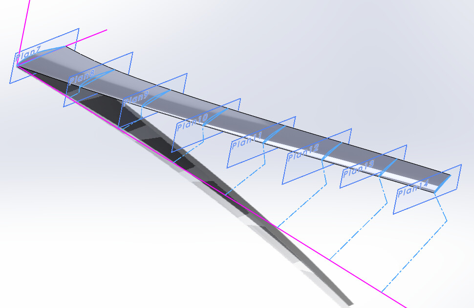
Macro modifiée, à télécharger plus bas, message 12…
3 « J'aime »
Holà merci à vous.
m_blt, merci pour ton dossier, les explications en plus, j’ai plus rien à faire alors 
Je vais essayer de comprendre et d’appliquer tout ça.
Toujours attendre le contrordre après l’ordre…
Quelques corrections de bugs dans la version ci-dessous, et l’ajout de deux boutons [Enregistrer] et [Ouvrir] qui permettent de sauvegarder et de relire un ensemble de données.
SW 2022 : Eppler387.zip (698,9 Ko)
Avec deux utilisations de la macro, on pourra prochainement faire de la concurrence à nos amis Yankees en matière d’avions furtifs…
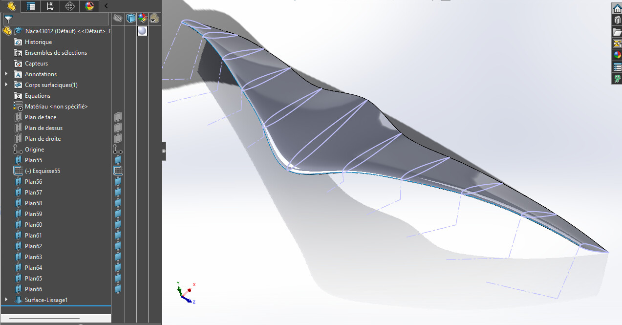
2 « J'aime »
Merci m_blt.
En deux mots pourrais-tu expliquer la liaison entre les différents points des profils et ta macro?
Comment as-tu recopié chaque profil sur les différents plans?
Bonsoir,
Chaque esquisse est basée sur deux splines, l’une pour l’extrados du profil, l’autre pour l’intrados.
Dans les deux cas, le point origine est le bord d’attaque du profil, et l’abscisse varie de 0.0 à 1.0, soit une corde du profil égale à 1.0. Il faut appliquer un facteur d’échelle aux deux coordonnées pour ajuster le profil à la dimension de corde souhaitée.
Dans la macro, toutes les sections utilisent le même profil avec ses deux splines, dans des plans parallèles :
- distants du plan de référence de la valeur du paramètre Position/Z.
- Les coordonnées sont adaptées pour tenir compte du décalage souhaité du profil suivant Position/X et Position/Y (notés decX et decY dans le code),
- de son inclinaison (Angle) autour de Z,
- et du facteur d’échelle.
Pour un point M de coordonnées (XM, YM) dans le repère du profil, les coordonnées sont (Xg, Yg) dans le repère général de l’esquisse.
J’ai supposé que le profil subissait d’abord la rotation autour de son bord d’attaque, puis les décalages decX et decY suivant les axes du repère du profil. D’où les relations :
Xg = ((decX + XM * echelle) * Cos(angle) - (decY + YM * echelle) * Sin(angle)) / 1000#
Yg = ((decX + XM * echelle) * Sin(angle) + (decY + YM * echelle) * Cos(angle)) / 1000#
Ci-dessous une vidéo pour illustrer l’utilisation de la macro.
1 « J'aime »
Super, merci!
Si j’ai bien compris tu pars d’une page blanche avec l’esquisse 3D1?
Donc si je pars de ton fichier je supprime le lissage, les plans et les esquisses mais lorsque je fais ça l’esquisse3D1 disparaît aussi.
Bonjour,
Sur l’exemple fourni dans le zip, l’Esquisse3D1 a été construite « à la main » après exécution de la macro, pour me permettre de valider certaines propriétés de la géométrie.
Sur l’exemple de la vidéo, je l’ai construite avant d’exécuter la macro : ce sont trois segments parallèles aux axes du repère général de Solidworks.
Mais il est tout à fait possible de partir d’un modèle entièrement vide.
Il y a dans le zip tous les documents pour réaliser la pale de mon exemple :
- les fichiers de profils extrados et intrados (*.txt , pour un Eppler et pour un NACA)
- les fichiers de données (*.dat, là aussi pour les deux profils)
- le code de la macro (*.swp)
Il suffit de suivre les étapes de la vidéo.
Je te demandais ça car le programme se plante après avoir créé le premier plan alors j’espérais que c’est parce qu’il manquait l’esquisse3D1 même si elle ne semble pas intervenir dans la macro.
Je n’ai pas de message d’erreur pour le path des fichiers, il crée le premier plan puis paf il se plante.
Bonjour ,
Si votre version de Solidworks est bien 2006, comme indiqué dans l’un de vos premiers messages, je ne suis pas surpris que la macro ne fonctionne pas… Faute de frappe ?
J’ai créé la macro avec l’environnement de SW 2022. Si votre version est plus ancienne, certaines des fonctions utilisées dans le code peuvent ne pas exister…
Quelle est votre version de Solidworks ?
Immédiatement après la création du plan, c’est le tracé de l’esquisse qui est lancé, avec d’abord la lecture des fichiers de profil. S’ils ne sont pas trouvés, un message d’avertissement devrait s’afficher.
Si ce message n’apparait pas, c’est que les fichiers existent. Il peut alors y avoir une erreur de lecture si le format des données est incorrect. Aucune vérification n’est faite en cours de lecture, mais dans ce cas, VBA devrait envoyer un message d’erreur.
Au delà, ce sont les paramètres de la section qui sont lus dans le tableau. Là aussi, risque d’erreur si les valeurs ne sont pas numériques.
Quels fichiers utilisez-vous ? Ceux que je vous ai fournis, ou de votre création personnelle ?
S’il s’agit d’une version perso, transmettez moi les fichiers (.txt) de votre profil et la sauvegarde (.dat) de vos données.
Pour identifier précisément le problème, la solution consiste à exécuter la macro en mode debug depuis l’éditeur de macros VBA. Quand une erreur se produit, l’exécution est stoppée et la ligne de code en erreur est affichée en surbrillance.
Etes-vous en mesure d’utiliser l’environnement d’édition des macros VBA ?
Si oui, sur quelle ligne se produit l’erreur ?
Difficile d’aller plus loin sans connaître plus de détails sur votre projet et sur vos tentatives d’exécution de la macro…
Arf comme souvent en programmation, c’est une bêtise qui est responsable du plantage.
Je suppose que tu as des paramètres régionaux Windows différents des miens, décimale « . » et moi j’avais « , ».
En changeant ça, les profils sont apparus Encore mille fois merci pour ce superbe boulot et l’apprentissage d’un nouveau domaine pour moi.
Nos messages ont dû être écrits en même temps car je n’avais pas encore vu ta réponse.
Comme dit dans le message précédent c’était un problème de décimale.
J’utilise la version 2026 là, j’ai choisi d’autres profils Naca et ça marche nickel.
Maclane et Fred je vais me pencher maintenant sur vos méthodes comme je ne les avais jamais rencontrées.
Merci à vous.