C’est insultant… Pas d’IA pour @m_blt … c’est l’IA qui devrait utiliser les macro de @m_blt pour être efficace !
3 « J'aime »
Bonjour,
Désolé @m_blt si j’ai pu paraitre insultant. Etant débutant en VBA et n’ayant pas vocation à en faire mon métier, l’IA ( et les tutos vidéo aussi ) m’aident quand même pas mal à appréhender les différentes fonctions utilisées dans les macros et à faire des choses par moi même. un grand merci @m_blt pour tous les codes que tu partages et le temps que tu y passes dessus.
Bonjour @Jonathan_VIALLE tu peux te détendre, personne n’a vraiment cru que tu voulais être désobligeant, ma remarque n’était pas à prendre au 1er degré ![]()
Bah! @m_blt est une de nos intelligence Non artificielle depuis au moins le 11 Janvier 2000. (en Avance sur son temps).
1 « J'aime »
Merci pour ces compliments, le rouge me monte aux joues…
Aparté pour @Maclane : inutile de me vieillir plus que de raison, mon inscription date de 2020 ![]() .
.

Me soupçonner de consulter une IA n’a rien d’insultant, il m’est déjà arrivé de questionner ChatGPT ou Le Chat, essentiellement comme outils de recherche dans les fonctions de SW.
Un exemple typique ici : « Quelle fonction des API de SW permet de générer une hélice? ».
La réponse de ChatGPT :
La fonction CreateHelix ou la méthode CreateHelixFeature de l’objet IModeler
Tout ceci est pure invention, aucune de ces fonctions n’existe.
La structure HelixFeatureData évoquée plus loin dans sa réponse a une réalité.
L’exemple qui vient ensuite paraît plus séduisant avec la fonction correcte InsertHelix(), mais dont les paramètres sont dans le désordre et incorrects pour certains.
De son côté, Le Chat propose de créer une hélice, courbe fondamentalement 3D, dans une esquisse 2D. Sans commentaire…
Puis de consulter la documentation de l’API SolidWorks pour plus de détails !
En général, beaucoup de temps passé pour un résultat aléatoire. Même si je reste convaincu que ce n’est qu’une question de temps pour que l’IA devienne performante dans ce domaine précis.
Les autres sources d’inspiration, plus efficaces :
- l’aide des API SW, notamment les exemples, ainsi que ceux de codestack.
- les macros générées par SW lui-même, même si l’abus du type Object pour les variables oblige parfois à des recherches fastidieuses pour trouver leurs types précis et leurs membres.
Et quelques années de pratique, même si c’est dans un autre cadre que celui des API SW et de VBA…
4 « J'aime »
![]()
![]()
![]() Désolé pour les 20 ans de plus !!!
Désolé pour les 20 ans de plus !!! ![]()
![]()
![]()
Mais que veux-tu :« Le talent n’attend pas le nombre des années. »
Je suis d’accord avec toi sur l’usage des IA Vs aide des API SW + CodeStack … Autant l’IA n’est pas (encore) parfaite et si elle se met à halluciner, comme en créant des fonctions inexistantes dans les API, c’est peine perdue. Mais ce n’est qu’une question de temps.
Mais l’apprentissage, à mon sens, ne devrait pas être fait avec des IA mais avec personnes réelles qui ont un vrai raisonnement et une bonne expertise … ou au pire via des sites « sérieux »
…
En revanche je me sert de l’IA pour commenter mes codes… là l’IA n’est pas trop mal et surtout elle fait beaucoup moins de fautes d’orthographe que moi… ![]()
Bonjour, dommage que tu ne puisses pas ouvrir les fichiers. Dans le fichier .part, j’ai une esquisse avec tous les paramètres permettant de définir le profil de dent.
Ensuite j’ai une esquisse pour récupérer le profil de dent et créer une répétition ( base du bloc créé ultérieurement ).
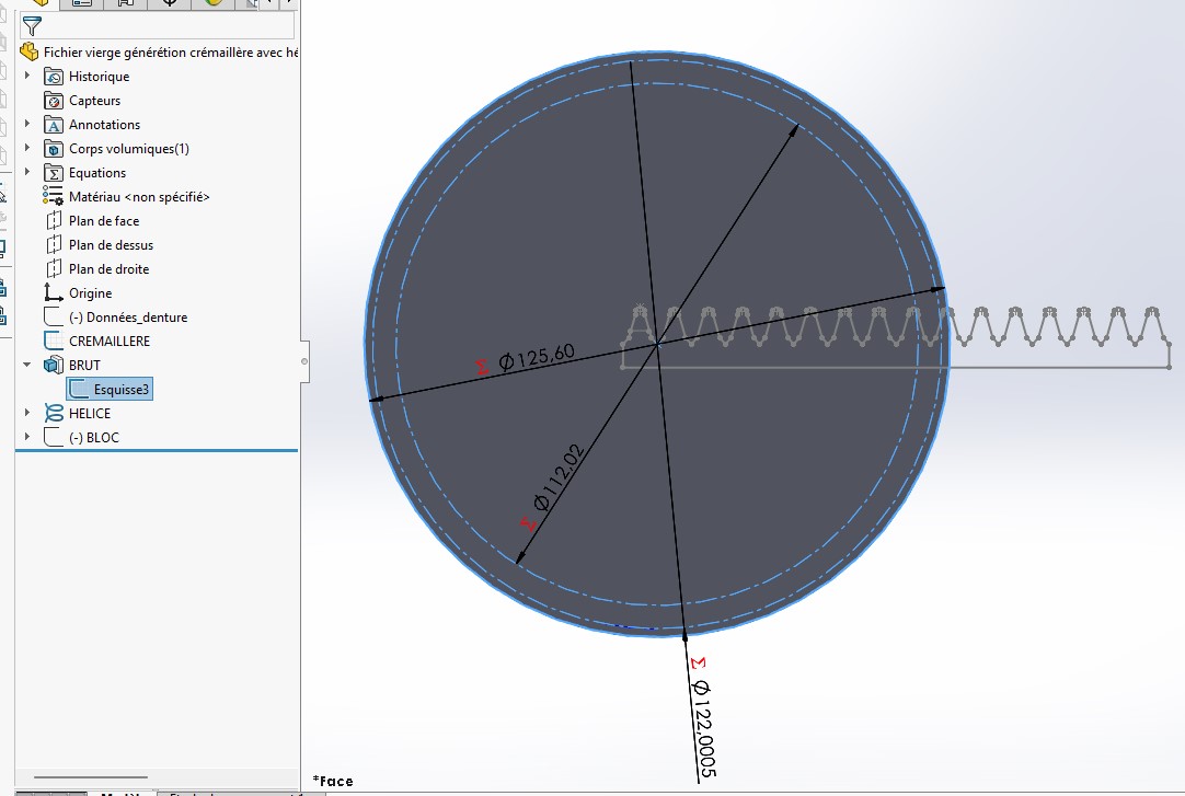
Après je crée le brut avec Ø pied, Ø tête et Ø primitif.
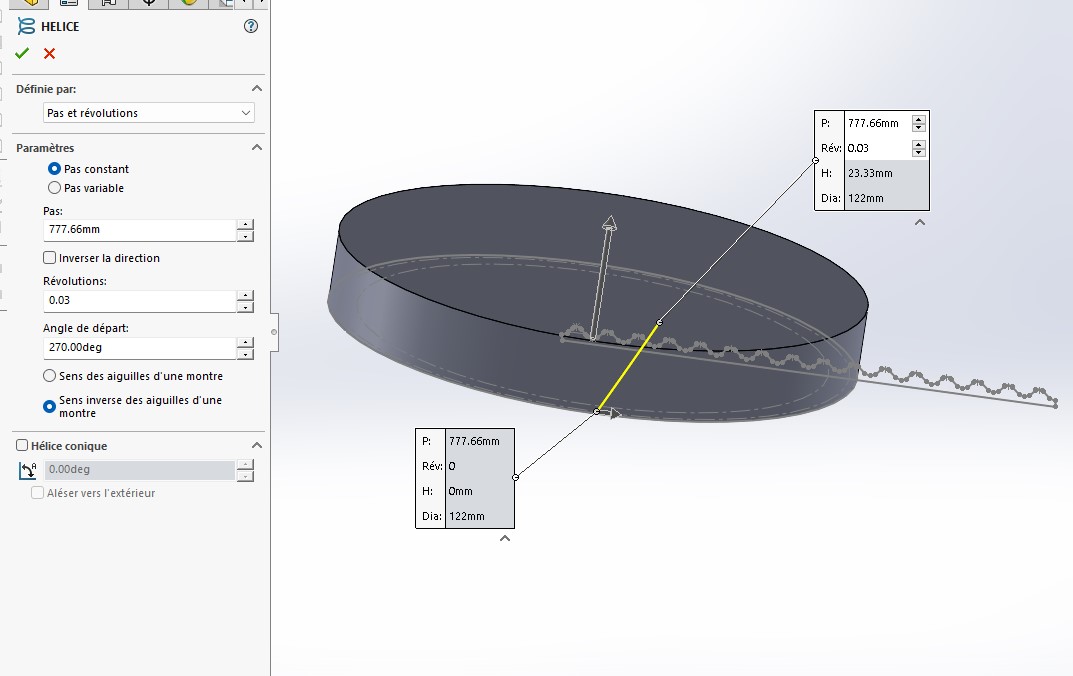
Ensuite je crée l’hélice avec les paramètres qui vont bien pour mon cas ( je les calcule dans ma 1ere esquisse Données_denture mais je n’arrive pas à les récupérer pour les utiliser dans le paramétrage de l’hélice, les champs de données n’acceptent que des valeurs numériques ). Le cercle de base de l’hélice est le Ø primitif qui est converti à partir de l’esquisse du brut.
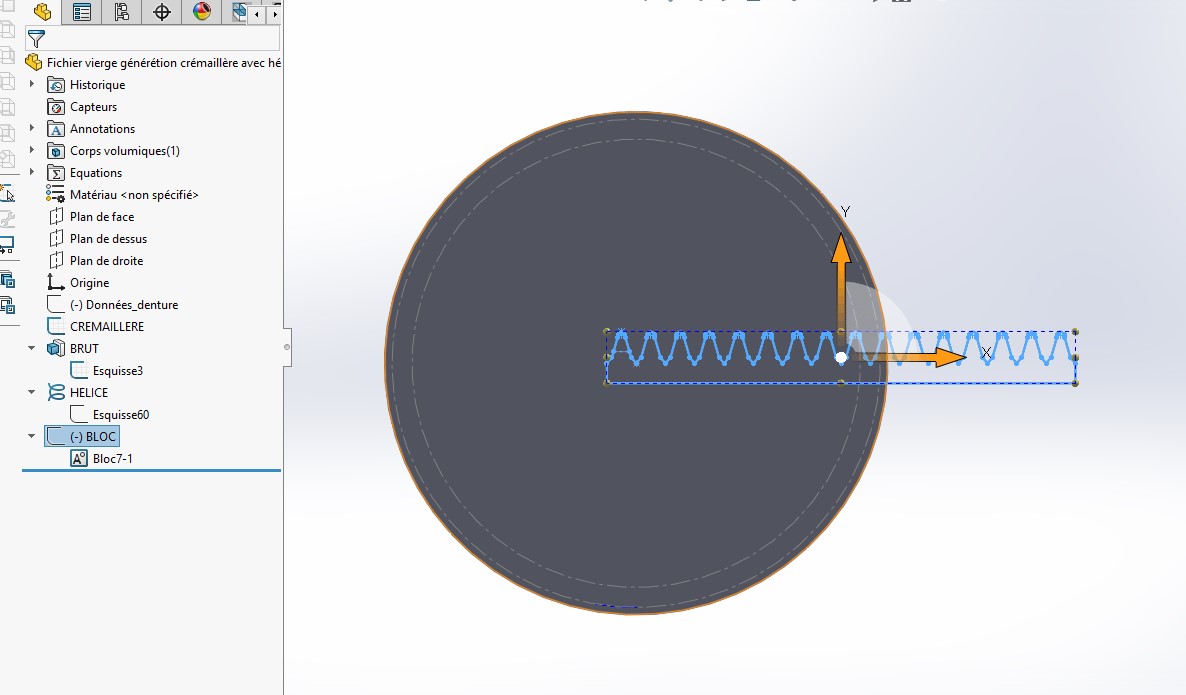
Enfin je crée une esquisse BLOC dans laquelle je récupère la crémaillère et la transforme en bloc. Je fais celà pour ne pas « casser » mon esquisse crémaillère et pouvoir revenir en arrière sans avoir à tout reconstruire.
Lorsque je lance la macro
Generation crémaillère denture hélicoïdale.swp (77,5 Ko)
Les coupes balayées se font toujours suivant la même hélice.
J’ai essayé de comprendre comment tu faisais pour répéter les hélices pour l’intégrer à la macro mais je sèche… En plus je pense que dans mon cas, je dois récupérer l’hélice existante afin d’en copier les paramètres pour les répétitions et là je sèche encore plus.
Bonjour
Si ton profil de dent est l’esquisse-quisse cache sous le gros tas de cotations, il ne me paraît pas être un profil valide (ou du moins pertinent) pour ton hélice.
Bonjour @Jonathan_VIALLE ,
Je n’ai pas mon PC habituel sous la main, et celui dont je dispose est limité à SW 2023. Je peux charger la macro, pas le document de pièce…
Mais, sauf erreur de ma part, ta version 2024 a la possibilité de sauvegarder au format SDLPRT de 2023 ou 2022, en faisant un « Enregistrer sous ».
Si c’est bien le cas, poste ta pièce dans l’une de ces deux versions, je regarderai ta macro dès que possible…
Fichier vierge générétion crémaillère avec hélice - AMELIORE SW2023.SLDPRT (195,7 Ko)
Fichier vierge générétion crémaillère avec hélice - AMELIORE SW2022.SLDPRT (196,2 Ko)
Voilà ![]()
Bon week end
Bonjour @Sylk ,
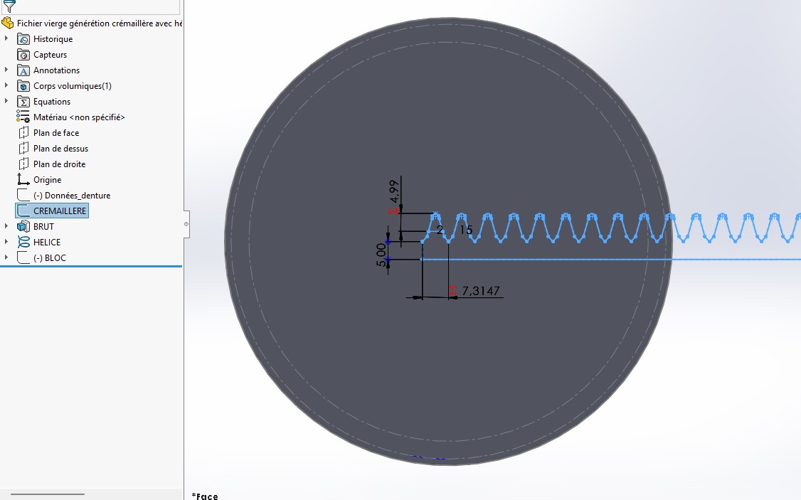
Pas de malaise: l’esquisse représente le profil de dent, répété en N exemplaires, pour définir la crémaillère chargée de l’usinage de la roue dentée.
L’hélice est la courbe que doit suivre la crémaillère pour générer la denture.
Hélicoïdale comme son nom l’indique.
Le tout en faisant en sorte que la ligne primitive de la crémaillère roule sans glisser sur le cercle primitif du pignon. Bref, un casse-tête cinématique, à combiner avec le casse-tête Solidworks, marié au casse-tête de la macro VBA.
La solution existe…
Salut @m_blt
Ce que je voulais dire c’est que, à mon niveau limité de connaissance, un profil, à plus forte raison répété, devrait ressembler à ce tracé vert plus qu’au tracé rouge :
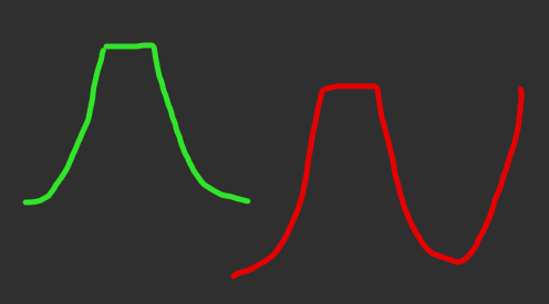
Peut-être me trompe-je.
Ou alors je n’ai rien compris à la question, ce qui est très probable.
Bonjour @Jonathan_VIALLE ,
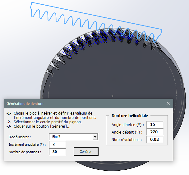
Rien de bien neuf dans la macro jointe, elle reprend quasi à l’identique le principe de celle postée précédemment.
A chaque pas du calcul, il faut positionner deux éléments :
- la crémaillère (bloc d’esquisse), et
- l’hélice (courbe) qui sert à piloter l’enlèvement de matière balayé.
Le principe fonctionne, mais l’utilisation du balayage le rend plus sensible aux refus de calcul SW que la version à denture droite qui utilise l’enlèvement par extrusion.
En dessous de 2 degrés d’incrément d’angle, la fonction est rejetée par SW pour certaines positions. Peut-être le fait de « zones d’usinage » minuscules qu’il a du mal à gérer. SW connaitrait-il la notion de copeau minimum…
Simplifier le profil de dent pourrait peut-être améliorer la chose.
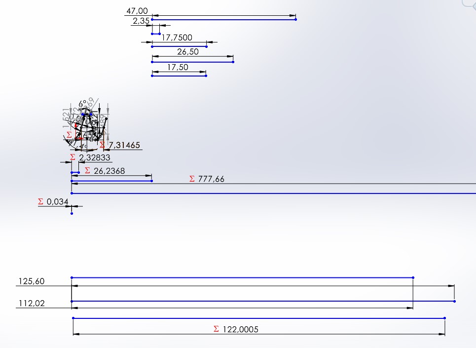
Une dernière remarque : le périmètre du cercle primitif n’est pas un multiple entier du pas de denture de la crémaillère. Voulu ou non ?
Generation crémaillère denture hélicoïdale.swp (110,5 Ko)
FichierGénérétionCrémaillèreHéliceSW2022.SLDPRT (4,0 Mo)
2 « J'aime »
Bonsoir,
Ce cas est un peu particulier car le module de l’outil ( et donc son angle de pression) est modifié pour obtenir un profil légèrement différent. L’angle d’hélice s’en retrouve aussi modifié, ce qui change légèrement le pas de l’hélice. Les données corrigées sont dans l’esquisse Données_denture et servent pour calculer le diamètre primitif sur lequel roule la crémaillère. Je pense que c’est pour celà que certaines coupes sont « dans le vide » si l’ incrément angulaire est faible.
EDIT : ça ne vient pas de là, tu as raison il y a des erreurs de construction.
Je passes de ça après la coupe suivant hélice 13
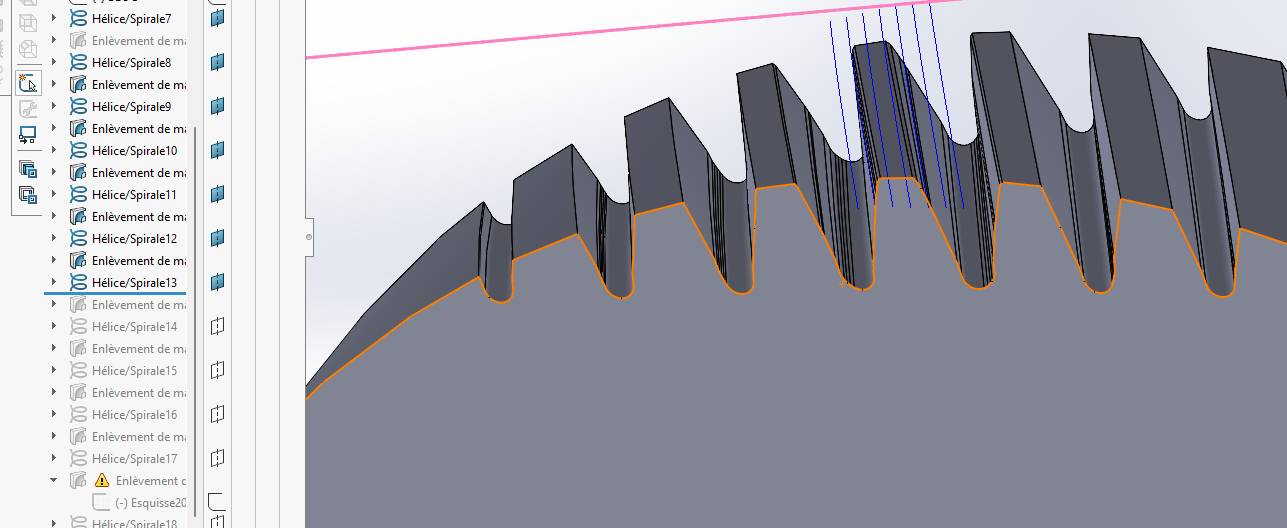
à ça à la coupe suivante:
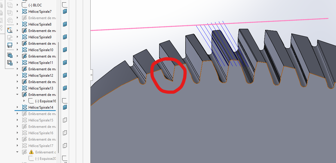
Penses tu que décaler le plan de départ par rapport à la pièce brute pourrait améliorer les choses?
Bonjour @Jonathan_VIALLE ,
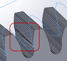
Je constate le même phénomène, une singularité apparaît après une quinzaine de pas (N+1), persiste au pas suivant, et devient monstrueuse ensuite.
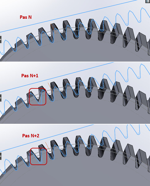
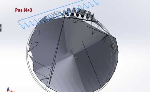
Je soupçonne des anomalies numériques provenant d’enlèvement de matière minuscules dans certaines zones, que SW a du mal à gérer, et qui le font disjoncter totalement.
En observant plus en détail les « usinages successifs », on peut noter que des anomalies moins visibles se produisent plus tôt dans la séquence : les génératrices du profil de dent convergent vers un même point…
Soupçon d’artefact numérique confirmé en choisissant un incrément angulaire plus grand (2.5 degrés), sur 40 pas : plus d’anomalie, l’aspect visuel de la denture est correct.
Je ne pense pas qu’un décalage du plan de départ puisse améliorer les choses.
ok donc problème difficilement résolvable…
Avec un grand incrément angulaire, la trochoïde obtenue est trop grossière. Mon but est de mesurer précisément le Ø de départ de la développante de cercle.
Je vais générer uniquement les esquisses et essayer de récupérer un « creux » de dent totalement généré ( à la main dans le pire des cas ). Cela me permettra d’avoir le Ø de départ développante. Ensuite je pourrai faire la coupe balayée d’une dent et la répéter pour obtenir la denture complète.