Bonjour,
Je souhaite créer une répétition d’esquisse en faisant varier certains paramètres. Par exemple, répétition d’esquisse de trous en faisant varier le Ø de ceux ci. Malheureusement, il n’est pas possible de faire varier les occurrences dna sune esquisse. Même sur une fonction, je peux changer l’incrément d’espacement mais je ne trouve rien si je veux un incrément concernant le Ø du trou.
Merci d’avance si quelqu’un peut m’aider…
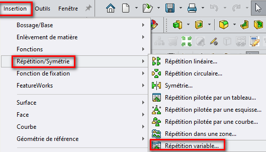
Je ne sais pas quelle version de Solidworks vous utilisez mais normalement il est possible d’utiliser « Répetition Variable » pour obtenir ce type de résultats:
La macro jointe permet une répétition d’esquisse d’un cercle avec accroissement régulier de son rayon. Et seulement d’un cercle, même si d’autres entités pourraient être envisagées.
Le seul mode d’emploi est dans la vidéo ci-dessous.
Peu de sécurités, il faut être vigilant au niveau de l’ordre de la saisie des entités.
Et pas de Ctrl^Z en cas de maladresse…
Bonjour et merci pour les infos. Malheureusement cela ne résous pas mon problème.
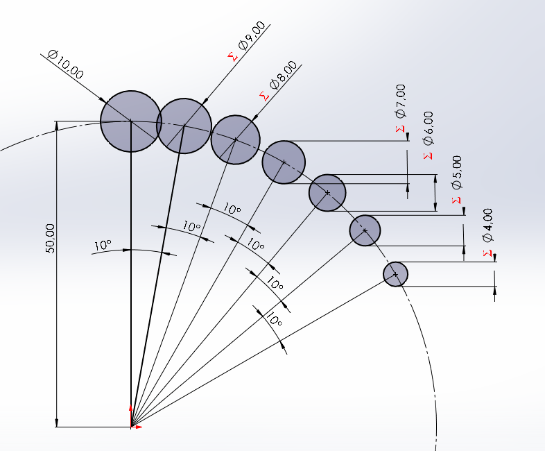
Pour être plus explicite, ci joint le fichier qui me pose problème. J’ai posé chaque esquisse manuellement, les angles et longueurs évoluant suivant des équations.
J’aimerai automatiser ce principe pour n’avoir à dessiner que la 1ère esquisse et de faire une répétition circulaire en faisant varier l’anle D1 et la longeur D2. génération Crémaillère.SLDPRT (2,5 Mo)
Quelle est la version de Solidworks de votre fichier ?
(A priori c’est supérieur à la 2022)…
Avez-vous essayé la répétition Variable avec un import Excel pour conserver vos équations ?
Je pense qu’il faut abandonner l’idée de faire vos répétitions dans une esquisse et les faire à partir d’une fonction (enlèvement de matière ?).
Bon je me peux pas ouvrir votre fichier mais je proteste … Vous voulez:
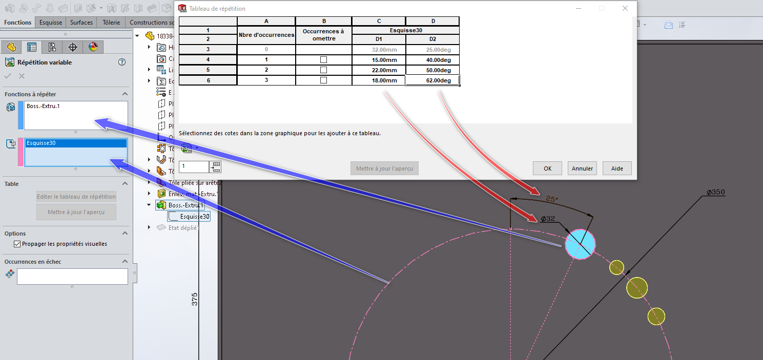
et la répétition Variable répond parfaitement à cette demande. (on peu y faire varier les diamètres ainsi que les angles (distance) de chaque occurrence, le tout dans une répétition circulaire…) j’ai dû mal comprendre votre question.
A fait, Super macro @m_blt . (Et oui les Macro et le CTRL+Z ne sont pas super compatibles.)
C’est la version 2024.
En effet je dois le faire avec une fonction et non une esquisse.
En passant par SW, je ne peux pas mettre des formules pour faire varier les angles et les longueurs. En créant un fichier excel qui calcul tout celà, ca devrait marcher.
Merci pour les conseils.
Apparemment, il s’agit de générer la denture d’un pignon à partir d’une crémaillère. On est loin de la répétition circulaire de cercles avec incrémentation du rayon…
Si j’ai bien compris, le but est d’implanter la crémaillère dans des positions successives d’usinage, en faisant en sorte que sa ligne primitive roule sans glisser sur le cercle primitif du futur pignon.
La crémaillère est définie sous la forme d’un bloc d’esquisse. Intérêt :
une seule entité, facile à implanter dans une esquisse par une fonction VBA,
la même fonction permet de définir la position du point d’insertion et l’inclinaison du bloc (plus besoin de cotation, sauf en cas de volonté de contraindre toutes les esquisses),
il suffit d’exploiter la condition de RsG en fonction de l’inclinaison pour définir les coordonnées du point d’insertion. En position initiale, le point d’insertion est placé au point de tangence des primitifs.
Il reste ensuite à répéter la fonction d’enlèvement de matière dans une boucle : environ une seconde par position.
Les paramètres à définir sont les suivants :
le rayon primitif du pignon par sélection du cercle primitif,
la valeur numérique de l’incrément de l’angle d’inclinaison,
le nombre de positions à générer.
Ça fonctionne, en révélant quelques interférences au niveau du pied de dent du pignon. Un déport de denture s’impose…
generationCremaillere.SLDPRT (1,1 Mo)
[Edit] Macro GenerationCr.swp (91,5 Ko) modifiée, téléchargeable dans le message suivant…
Bonjour,
Merci pour la réponse, c’est super intéressant.
J’ai une question ( les fonctions VBA sont un peu du chinois pour moi ). Ou se trouve le bloc utilisé pour faire les différents enlèvements de matière? Lorsque je supprime tout pour ne garder que l’esquisse dans laquelle se trouve le cercle primitif, la macro va chercher le bloc 6 mais je ne sais pas ou.
Je voudrais pouvoir dessiner la crémaillère dans un bloc, et ensuite générer les différentes positions de celle ci pour voir le profil obtenu.
Pour les interférences, je suis d’accord mais pas forcément gênantes, mon but étant de trouver le bon profil de crémaillère, afin d’obtenir le point de départ de développante souhaité et de « creuser » suffisamment en pied de dent.
A priori, un bloc est utilisable, en insertion, modification, sauvegarde en fichier, tant qu’il est présent dans une esquisse.
Si toutes les esquisses où il est inséré sont supprimées, il n’est plus accessible.
Dans la macro originale, le nom du bloc (Bloc6, lignes 64 et 66) était fixé en dur dans le code. Un message est affiché à l’exécution s’il n’existe plus dans le document de pièce.
J’ai apporté une petite modification à la macro qui permet de choisir le bloc dans une liste déroulante de l’ensemble des blocs disponibles dans le document de pièce.
Ce qui évite d’intervenir dans le code.
Avec ce changement, le bloc est trouvé même si les esquisses d’insertion ont été supprimées. Ce qui semblerait indiquer qu’il « survit » dans la base des objets de SW. Pas sûr qu’il soit encore présent après enregistrement de la pièce, puis fermeture/réouverture…
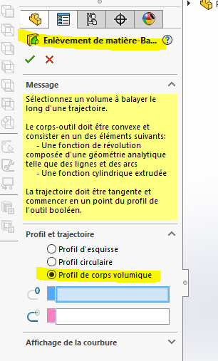
Ne serait ce pas plus simple de créer un fichier comme ci joint comprenant le volume de l’ébauche ainsi qu’une extrusion du bloc définissant la crémaillère, contraint tangent au Ø primitif et de répéter des extrusions en modulant l’angle et le déplacement de la crémaillère?
J’ai bien avancé sur la version de génération crémaillère pour une denture droite. J’essaie maintenant de faire une version pour denture hélicoïdale. Pour la version droite, chaque fois qu’une esquisse est créée, il y a un enlèvement de matière extrudé. La superposition de toutes les coupes donne la denture obtenue.
Pour la version hélicoïdale, je créé une hélice correspondant au pas de la denture à générer. Par contre lorsque je veux faire les répétitions du bloc contenant la crémaillère, les esquisses générées sont bien placées mais l’enlèvement de matière balayé se fait toujours sur l’hélice de départ. Je n’arrive pas à répéter l’hélice pour que chaque coupe balayée se fasse suivant une hélice dont le point de départ soit contraint à l’esquisse de la crémaillère. Je ne sais pas si je suis assez clair dans mes explications. Je voudrai pouvoir créer une répétition circulaire d’une hélice mais impossible de sélectionner cette fonction dans le menu répétition circulaire. Ci joint le fichier et la macro qui ne fonctionnent pas.
Bonjour,
Ces tutos permettent de faire des représentations graphiques de dentures. Je souhaite générer le profil d’une denture réel à partir de la définition de l’outil qui sert à la fabriquer.
Et après tu as juste à faire la répétition circulaire du nombre d’usinage.
NB : l’intérêt de cette fonction par rapport au balayage de section droite c’est que cette fonction génère aussi le volume enlevé par le talonnage de l’outil
En lançant la macro avec 0 répétitions ( 1 seule coupe ) et l’angle à 1° , c’est bon. Dès lors que je lance plusieurs répétitions, les coupes balayées se font toujours selon la courbe de l’hélice initiale et ça ne marche plus. Je veux que les différentes coupes balayées se fassent selon des hélices qui tournent de 1° à chaque coupe. Je n’arrive pas à récupérer les données de la courbe ( hélice ) pour qu’elle soit répétée.
Malheureusement, je ne dispose pas de la version SW 2024, ce qui m’empêche de consulter vos documents.
Ceci étant, il est clair que l’hélice utilisée pour le balayage doit accompagner la crémaillère dans son mouvement. C’est le paramètre StartAngle de la fonction InsertHelix qui permet de le contrôler.
A noter que les paramètres de cette fonction sont nombreux et peu clairs, comme souvent avec les API de SW.
La macro jointe reprend la précédente créée pour une denture droite, en ajoutant l’option de denture hélicoïdale, sous la forme de la fonction nommée « GenererDentureHelicoidale ».
Elle n’a été testée que sur l’exemple joint, donc sans garantie…
Merci, déjà la répétition d’hélice fonctionne. Je vais essayer de l’intégrer à ma macro.
PS : tu utilises une IA ? Si oui laquelle ? J’essaie avec chatgpt mais c’est laborieux.