SOLIDWORKS Routing 2026 SP1.1 – Hydraulic Hose: Unable to Orient a Parker Elbow During Insertion
Hello everyone,
I'm looking for help on the definition of an elbow fitting for example Parker for a hydraulic hose in SOLIDWORKS Routing 2026 SP1.1. Having about twenty years of experience with Autodesk Inventor, I am quite surprised by the complexity of this operation in SOLIDWORKS Routing, while the definition and orientation of this type of fitting is much easier to implement in Inventor for everything related to piping.
After several tests and exchanges with Visiativ support, I still can't get the desired behavior. In particular, I suspect a problem in the definition of the component or in the reference constraints to be applied.
1. Objective
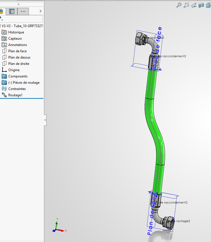
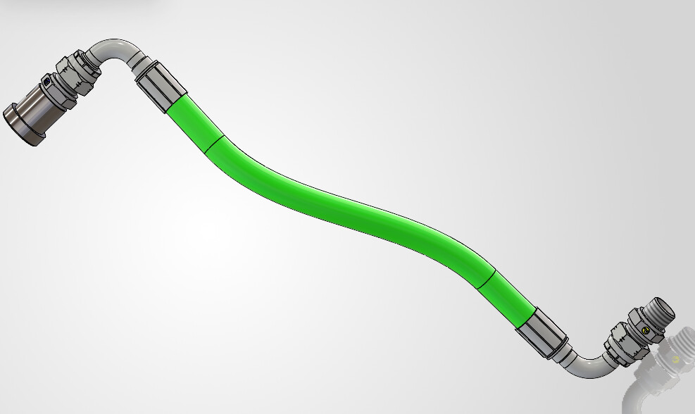
I want to create a hydraulic hose with crimped fittings, including a 90° elbow, with the following features:
- Automatic attachment of the fitting to the nipple;
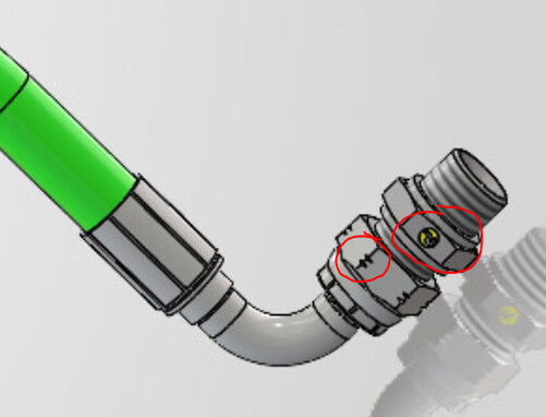
- Free orientation of the elbow during its insertion, in particular by
Maj + flèches gauche/droite; - Retention of the automatic hook without blocking the rotation of the fitting;
- Use of the component in a hydraulic hose routing.
The goal is to have reliable and reusable components in a hydraulic library.
2. Current Component Configuration
In the Routing Library Manager:
- Routing Type: Tube, used for my hydraulic hose application;
- Component type: End flange. I can't find a category called "end fitting" in the French interface;
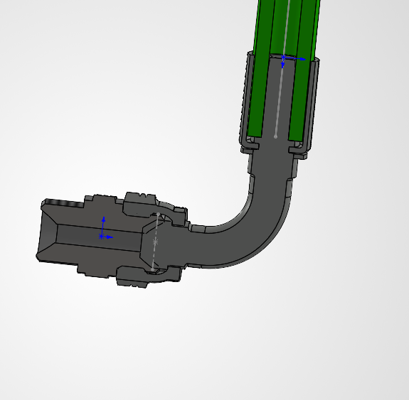
- Connection point on the flexible side: placed on a circular edge corresponding to the nominal diameter of the hose;
- Threaded Side Routing Point: Placed in the center of the other end of the elbow;
- Axis of rotation: defined along the axis of the cone;
- Vertical axis: Also defined from the routing point, as tested.
I tested different configurations of constraint references, with one, two, or three sets of references, as well as several geometric combinations.
The parameters are accepted and saved by the Routing Library Manager.
3. Problem encountered
The automatic hook of the elbow on the nipple works when the stress references are set.
On the other hand, rotation of the elbow during insertion remains impossible , even with Maj + flèches gauche/droite .
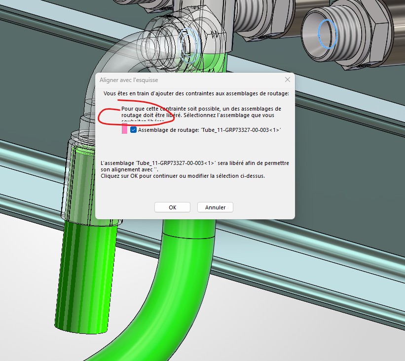
I also encountered difficulties in orienting and updating fittings in test assemblies.
The point that seems decisive to me is the definition of the constraint references: the automatic hook must work without removing the freedom of rotation of the elbow around its axis.
An additional difficulty comes from the connection geometry: the inner cone of the nipple is concave and the reference diameters of the nipple and the fitting are different.
4. Exchanges with Visiativ support
The bracket told me that the fitting should be set as an end fitting rather than a routing bend, and recommended:
- A single connection point on the flexible side;
- An axis named exactly
Axis of Rotation, following the axis of the cone; - Consistent stress references between the nipple and the fitting, with no third reference blocking rotation.
A file with the axis of rotation was also sent to me.
I've taken these indications and tested different configurations, but I haven't been able to get the expected work yet. I've asked for clarification on the exact constraint references used on the sample component, so that I can reproduce the configuration, but I haven't gotten those details yet.
5. My questions to the community
- Is the "End Flange" component type suitable for a crimped elbow fitting at the end of a hydraulic hose, which you want to orient freely during insertion?
- What constraint references should be defined in the Routing Library Manager to ensure automatic snapping while maintaining this freedom of rotation?
- Is there a particular configuration of the connection points, rotation axis, or vertical axis needed for this operation?
- Can the fact that the conical connecting surfaces are of different diameters, with a concave cone on the nipple side, influence the rotational behavior?
If anyone has already set up this type of hydraulic fitting in Routing, I would be particularly interested in a concrete example of a component definition or a precise explanation of the stress references to be used.
Thank you in advance for your help and feedback.
Sincerely,
Thomas ORTEGA
 , cela change des posts du type : « Ca marche pas! » sans plus d’informations.