Is it possible to create rigid connectors starting from a circle (or a cylinder), and converging towards a point?
My problem is the following: I have a compensator that connects 2 duct elements via flanges.
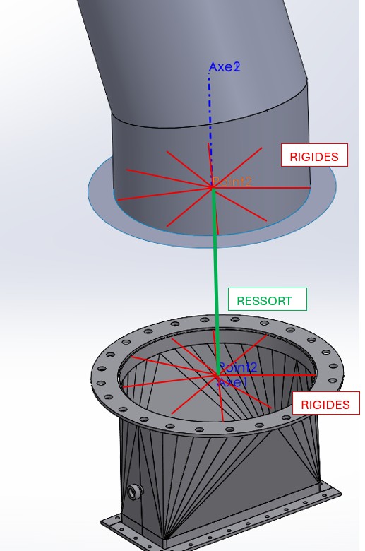
I saw that under simulation, the spring connectors to indicate the stiffness of a compensator only work on points/vertices. I would therefore have liked to rigidly connect the contours of the flanges towards their center. And connect the 2 centers via a spring.
Interesting question indeed. The simulation help shows things about the springs between the faces but nothing between points/vertices. The selection of the two sides does not suit you because you don't have the torsional/flexural rigidity?
Hello, If I understand correctly, you don't have DS Simulation to do tests and you would like to know if it is able to solve your problem. If this is the case, why not entrust this service to a design office? It will surely be less expensive
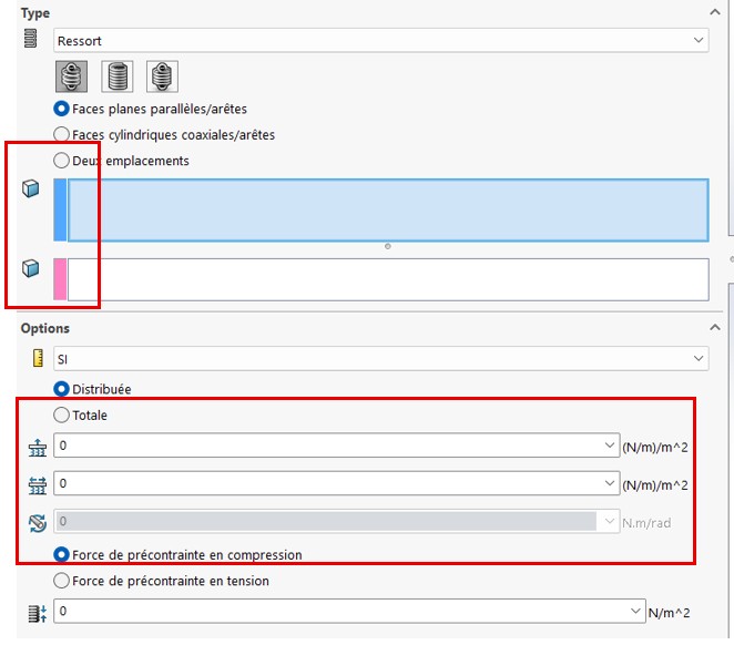
The Solidworks Simulation help indicates that spring connectors can act:
between two parallel flat faces, or
between two coaxial cylindrical faces, or
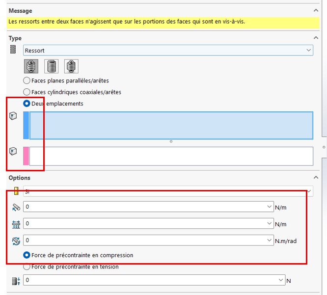
between two summits.
Judging by the image you offer, the first of these options seems to fit. What is the point of going through virtual rigid elements and a spring joining their centers?
The problem is that by going through the faces/faces option, you lose the possibility of indicating a bending stiffness of the spring (data known to my compensator).
By going through the vertice/vertex option, you can indicate the 3 stiffness (axial, lateral, flexion).
The bending stiffness of the spring connector between faces occurs naturally, due to the distribution of forces in the facing faces. The action of the connector is broken down into a set of elementary springs assigned to each facet of the mesh.
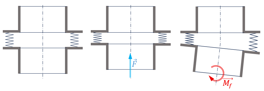
A displacement normal to the faces generates a force F normal to these same faces. And vice versa. rotation around a radial direction generates a radial moment Mf (bending). In this case, the bending stiffness is dependent on the axial stiffness and the dimensions of the bearing faces. This would typically be the behavior of a bellows. Can you tell us more about your " compensator ": type, dimensions, axial and radial stiffness...
Its problem is that you can't give torsional stiffness if you're plan/plane and according to the simulation help must manage a single big spring between the 2 faces (and not many small ones). So with the plan/plane modeling (which he could use with his model). I tried to look yesterday and it seems impossible to create the center point to the face under simulation. It would be a bit like a distant charge but for travel.
It must be worth making a request for improvement because at the moment T the spring between two points must be strictly useless (except possibly if you have a beam model) because there are quite few vertices in 3D models and a spring never sticks to it (it will hook on a cylinder most often → impossible to represent because it would require a virtual central point connected to the 3D model).
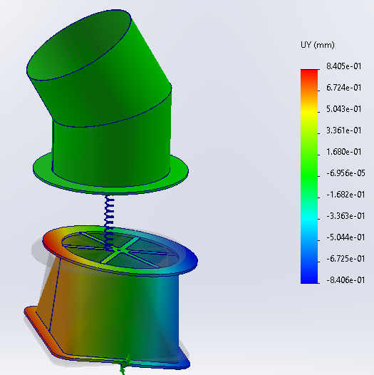
There are two ways to give an answer to the problem: -1- Based on the principle of the " rigid connector" hoped for: to generate a " spoked " body, joining the flat face of the upper component's flange to its center, a body that is not fused, and to create in its central part a shape detail placing a vertex in the center. Do the same for the flange face of the lower component. In the simulation, declare these two radiated elements as rigid, therefore non-deformable (right-click on the body > Make rigid). The spring connector can then be created between the two vertices of these radiating elements.
Disadvantage: the flanges of the upper and lower elements are locally stiffened by these non-deformable radii, the areas in the vicinity of their ends will remain coplanar. It may be without major disadvantage if the flanges have significant rigidity.
-2- Create the " compensator " component in the form of a volume body, and treat it as such in the simulation.
This solution is more satisfactory in principle, but it is necessary to have the geometric model of the object...
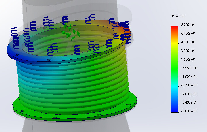
At the calculation level, discretizing the compensator by replacing it with 10 (or more) plane/plane springs connecting portions of the 2 flanges shouldn't be too messy: the springs can crash/lengthen differently and you have to fall back on a flexural rigidity (not sure that it gives much in torsion though). I would say that it is probably less bad in terms of modeling than the rigid star body of @m_blt Modeling the compensator is probably the best, but it will give a cumbersome model (the corrugations have fairly small radii with thin sheet metal → problem mesh). Modeling the compensator as a shell element would surely make sense in this case (more chance of having a mesh that passes, consequent reduction in the number of global nodes).
I agree that the star body is not a very satisfactory solution, insofar as it stiffens the flanges of the ducts... But it is this type of element that @Emmanuel_soulier was looking for in his first message. If not, what else, George would have said? Hence the idea of simulating the compensator itself.
This is exactly what the connector does when it comes out between parallel planes, continuously (or almost, within the limits of the mesh). Excerpt from the SW Simulation help: Total Option ===> The total stiffness is distributed evenly over the selected shell faces or edges.
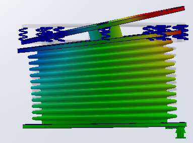
On the illustration below, I installed a spring connector with only an axial stiffness between two parallel faces, one on the compensator, the other on a rigid component placed on top, to which a tilt of about 1 degree is imposed. If the thrust of the spring were purely axial, the bellows would not have this shape, " compressed " on the left side, " stretched " on the right. This confirms that the spring does indeed exert a bending moment on the compensator.
Torsional stiffness : With a bellows-type compensator, the torsional stiffness must be considerable. If torsional defects need to be compensated, the choice of another type of bellows seems essential to me.
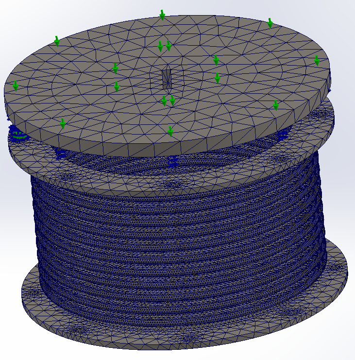
Weight of the compensator simulation : the geometry of the compensator/bellows is certainly tortured, but the static simulation only takes about a minute with a relatively fine mesh. Nothing unacceptable. Especially since the aim is to validate the " Spring Connector" as a satisfactory model of the compensator. On the overall structure of the duct network, the " geometric " compensator will not appear, replaced by a spring connector.
I had in mind that this kind of elements was greatly simplified (like only 1 element connected to the 2 planes considered rigid). If not, it must be usable.
Is your compensator modeling volume or surface? 1 minute does indeed seem quite fast.
Model entirely " built by hand ", based on images gleaned from the internet. All in volume, for geometry (bellows diameter 400 mm, thickness 1 mm) and for simulation.
Ideally, you would have a model from the manufacturer... As for the minute for the simulation calculation, it is without the mesh (about 25 s), and on a good " gamer " laptop.
Thank you for all your answers helping a lot to think! After talking to visiativ, we decided on the solution of creating a rigid " fictitious " surface at the flanges to connect the spring to the center of the face and thus be able to take into account the torsional stiffness of our compressor.
If time permits, we will do the exo to compare the results with a modeling without this plate and going through the front springs as presented by m_blt.