Bjr
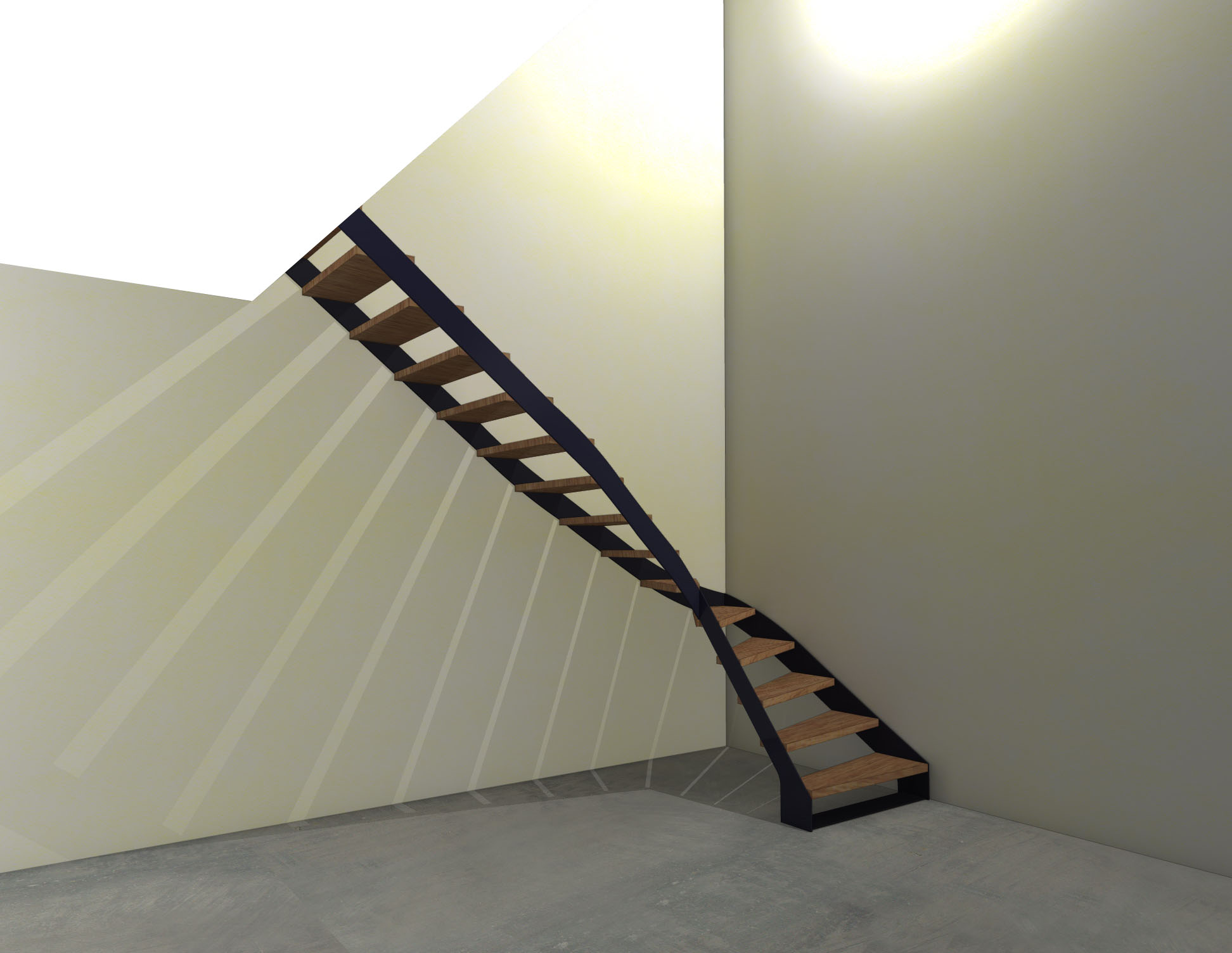
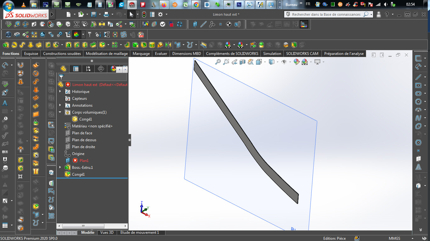
Attached is a pack and go of a 1/4 rotating stair stringer, it is the largest stringer which is against a plasterboard partition, so no fixing possible..., also for an aesthetic concern, the material height of the stringer is reduced..., I made a simulation of this stringer and if someone could tell me if it is realistic, In the nails, I start the cutting, thank you in advance
Sincerely, P
Simul limons.dxf (17.7 KB)
Simul stringers. SLDPRT (89.5 KB)
Ierre

Attached is another pack and go for all the interior stringers/simulation, again the same is the simulation realistic?, also the errors of the plans are from the model ref deleted to lighten the SW file
INTERIOR SILTS-simulation. SLDPRT (168.9 KB)
Hello
You know how much we appreciate you on this forum, but personally I can't follow you in your approach.
For the following reasons (sorry  )
)
Personal opinion: everything will collapse and worse as soon as two people get together
1°) You can't make a realistic simulation just on one side in 10 mm thickness over 3 m in length.
2°) the dimensions in relation to the steps are weird (the scalers will surely tell you that your number of steps is not good.
3°) The fact that you have no support on the plasterboard wall will create unbearable spills and shocks from the plasterboard. And I'm not even talking about the fixings at the top and bottom of the stairs (hello the anchors at the bottom and at the top it's even worse)
4°) it is only the wall stringer + stringer in the void + the step fasteners attached to the wooden planks (which are also very thin without risers) that can be the subject of a global simulation.
5°) something impossible to do with SW (and all other software) is a simulation with wood (impossible to have the resistance criteria of the young Young and his other friends.
Conclusion: tell me in secret (who do you want to get rid of by making him go down the stairs  ).
).
You have to completely review your design according to the rules of the art of stairs which have standards that are not easy to respect as soon as you do in the design.
Kind regards
Sorry for the delay... too much work,
I replied via email, thank you Zozo_mp
Hello Zozo_mp,
I haven't answered all your questions/thoughts, namely, why is it impossible to make a simulation of the + large stringers, indeed it risks " spilling ", something that sw does not take into account since I am the one who should have parameterized a torque rather than a force, right?, in fact it is above all the flexion that I want to know, also the steps will hold the stringers together even if it means adding a metal reinforcement/connection under a step in the middle between stringers and perhaps under the step which is angled. A post/angle iron in the corner/walls is planned...
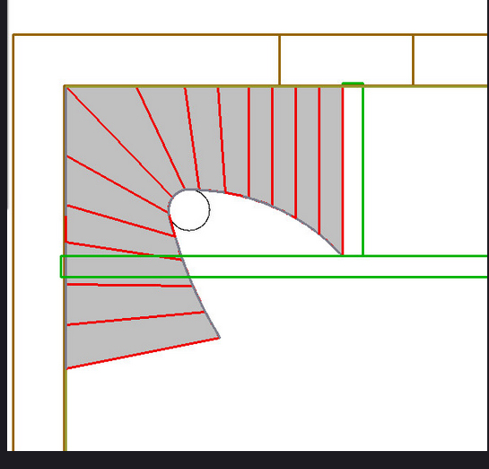
For the heights of the steps as well as the treads, in fact no choice, because the starting flight cannot be longer because there is a French window that I did not materialize on the rendering, for many architects, alas, a staircase is a waste of space, they minimize the hoppers...
The anchors on the ground and at the top against the hopper are made with 2 strips of sheet metal of 10mm thick. connecting the stringers, and 6 diam metal dowels. 14mm per sheet, in concrete, no worries...
And yes, to make a real simulation, you would need the staircase in its entirety, only for the wood, Young's modulus...
Thank you again, what a pleasure to exchange with you!!
I love your comment about whether I want to get rid of someone...!!
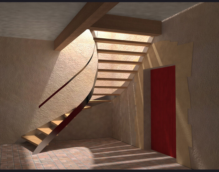
Attached are 2 images of a staircase, variable step that ends at 1.70m, with to be able to escape the beam at the beginning a variable tread, again not too much choice..., sometimes I use the handrail/railing to stiffen the staircase...
Sincerely, Pierre
Hello @pierre32.debat
I gambled to see how to solve your pb.
To be able to do the simulation, it is imperative to have the wall stringer and the exterior stringer.
For the problem of wooden steps, we must be able to get around the PB by putting fixed connections at two points to replace the steps. But you should add at least in your model the metal parts that fix the wooden planks and which are I guess screwed or welded on the stringer.
You should also have the pieces that fix the stringer at the top and bottom.
If you provide the complete asm we could look at how to make you a simu that holds up.
For this asm you can replace the wooden planks with 1 mm sheet metal. This will hold the ASM and we will exclude them from the simu.
Small remark: in fact I use force because it is comparable to a weight. But in fact, in the case of stairs or platform that receives staff, I use remote charging with a gravity. Because in fact you can't put more than one person of 95.752 kg every 3 steps to know the maximum theoretical load that your staircase must support (5 people max in your case. This maximum value may seem absurd but the number of things that collapse because we don't predict the unlikely case are more frequent than we think.
Good! so you make us a nice complete ASM (including the screw holes) with a pack-and-go, all zipped and we get back to you.
Kind regards
PS: for the handrail you can ask a police station 

Here I am again for this staircase,
With a few changes, back to " normal " stringers, the steps that protrude from the stringers do not please Madame..., - less chance of ending up on the violin, too bad!! -, plus, attached some details about the attached PDF, I'm going to try to make you a SW file, but in assembly mode I'm a beginner, the opportunity to progress you give me!!, I'm going to import in DXF into SW the entire model and extract the parts, well, I don't even know if it's the right method, see well or badly!! See you later, I'll rest a little, though!!
Thank you again for your precious help!!
d@t détails.pdf (604.8 KB)
I can't sleep, this staircase occupies ..., anyway, so I said, I imported the Dxf from the model, it's fine, not too heavy and well arrived -72 GB of ram and 2 3.6ghz processors of 8 cores each, thanks to the technology, also I create a 2d sketch on a plan previously chosen according to the part to be modeled, Then I convert the entities and extrude/bump!! Then I remove all the constraints of the sketch to be able to remove everything from the import model, and I save the part thus obtained in SW, is it a good method, is there a better and + faster way?
Only downside I find myself with more ref for the plan created, it's not ideal, I could keep/create points to do this, right?
Ps: I don't care about the tangencies yet, I'll refine before cutting, ... not the head, nor the teeth!!
Here is an assembly, some errors of the order of 0.8mm, dxf from Arc+..., + me too..., in short
Is this acceptable for a simulation, although the assembly has bright red!!
I still post the zip
See you + later
Assembly 1.zip (2.4 MB)
Attached is the plan in dxf, dimensions written in meters
One more night with Kim ..., it's better than at the junk!!
Plan2C.dxf (50.4 KB)
I just realized that the swinging of the 2d plan is not the right one - the carpenter wants to minimize the balanced steps -, on the other hand the dimensions/dimensions are the right ones, here attaches the dxf of the 3d
stairs only export.dxf (928.2 KB)
Hello @pierre32.debat
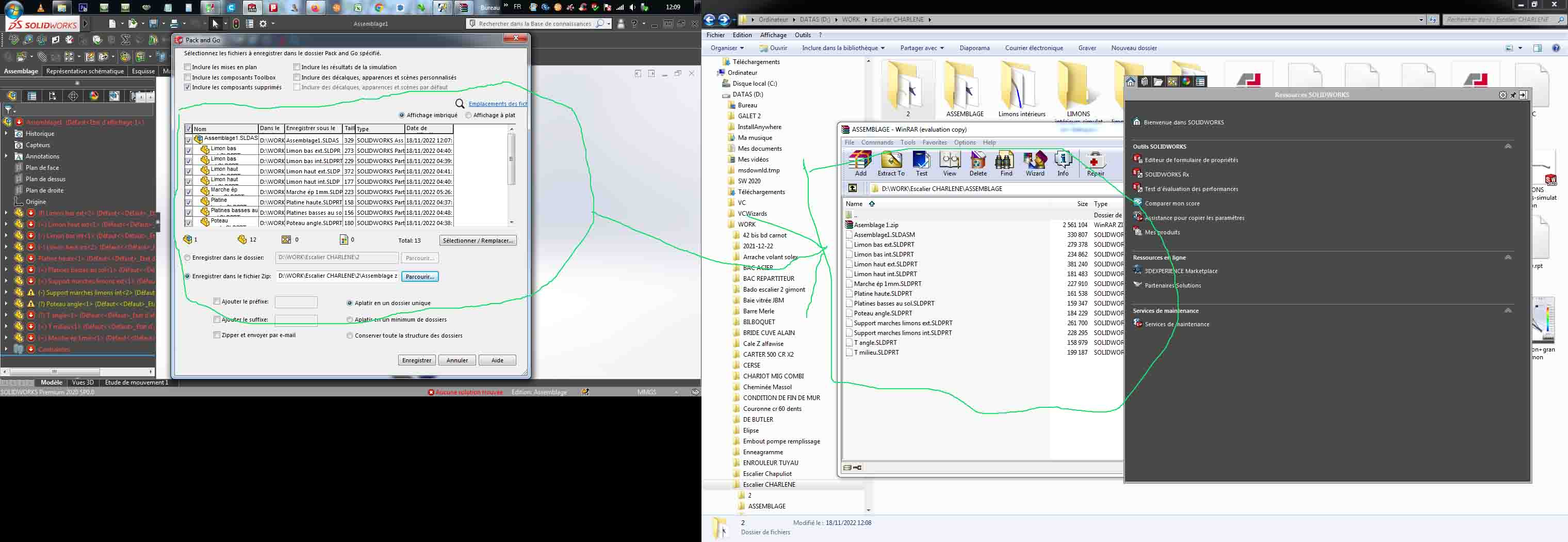
You should send me back your ASM file by doing a PAck and GO
do File ==> Pack and Go ==> then check Zip and everything else that is needed.
I was still able to open the asm and my point of view if you allow it and that we need to improve in several places otherwise it won't hold: especially on the external stringer.
These modifications should be made before the AMHA sim.
Kind regards
Well received, if so, I was able to rectify some errors in the assembly, tendency to put too many bad constraints!! I'm learning!!