Hydraulic turbine rotor simulation

Hello

I'm busy simulating a hydraulic turbine rotor in SolidWorks, but I'm having a problem with the imposed displacements that is distorting my results.

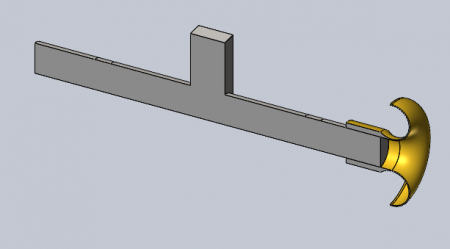
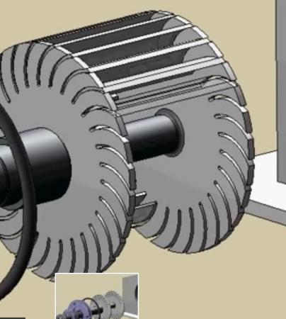
I can't share the model, but here's an overview of the problem.

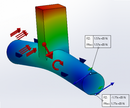
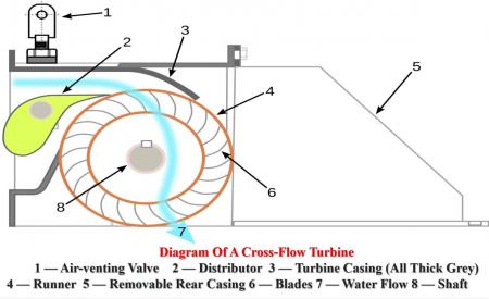
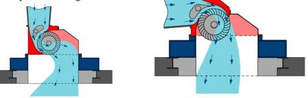
The challenge is to simulate the action of the fluid on the rotor blades. To do this, I determine a pressure to be applied to the blades that generates the desired torque. Only the blades facing the intake area are subjected to pressure. The rotor is supported by 2 self-aligning bearing supports.

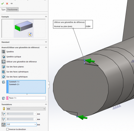
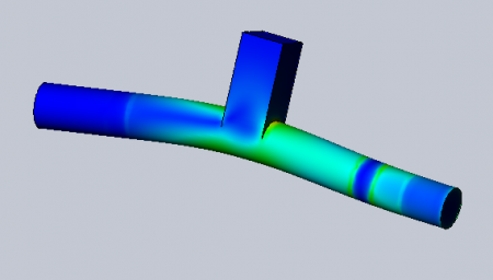
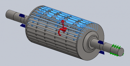
My problem lies in the imposed displacement to block the rotation. The only solution I have found is to block the rotation of the cylindrical face on which the flexible coupling is fitted, but this also hinders the radial displacements as well as the alignment of the axis. The cylindrical face of the coupling is in this case considered as a slide blocked in rotation, which does not correspond at all to reality (the end of the shaft carrying the coupling is free). The simplified model illustrates the problem well.

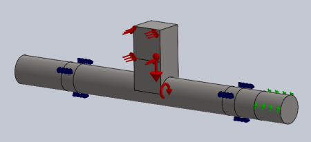
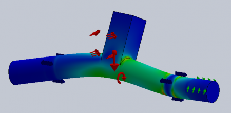
Do you know of a way to lock the spinning shaft "relative to itself", i.e. by preserving the degrees of freedom in the radial plane and at the alignment of the axis? Or do you see another way to simulate my problem?

It is obviously not possible to apply a resisting torque corresponding to the torque generated by the pressure on the blades (even with 2 identical opposing torques, SW cannot calculate).

Thank you in advance for your ideas and suggestions.

I am attaching the simplified template.


rotor_shematise.sldprt

Hello

Your result is not necessarily that badly representative: there will be a difference in behavior between the tree linked to your generator and the one that only does the guidance (it can rotate freely and the efforts will not go to its side).

You can optionally lock your rotation on an extension of the shaft you have blocked. You make an extrusion of a much smaller diameter and you block the rotation on the end of this diameter. The added shaft end will have crazy constraints and a lot of displacement because of the torsion but the modeling of the behavior of your shaft will surely be a little more accurate (be careful that the rotation does not create problems in terms of the application of your force)

2 Likes

Hello

This approach is a little different from that of the flexible shaft proposed by @froussel.

It would be interesting to know by what means the "couple" is transmitted to the receiver, in order to confirm that it is indeed a couple...
No torque-type support in the SW simulation module. To get as close as possible, we can think of two diametrically opposed point supports, at the level of the exit face of the shaft, with a normal tangent to the edge of this face.
This objective is achieved by doing a small machining to locate the two points and by suitably choosing the reference surface and the associated displacement (zero according to z). Which amounts to reinventing the double key...
   
The calculation is proceeding normally, and the display of the results shows that the points in the end zone are being moved in all three directions.

One downside: if we look at the results, we can see that the two "one-off" efforts do not have the same standard, which proves that they are not quite a couple.
It is possible to play on the value of the displacements following z at the level of these two point supports to make the standards identical (about 0.004 mm, the shaft is very rigid with regard to the forces applied). This confirms that the face at the end of the shaft moves slightly along z if the receiver exerts pure torque. Which brings us back to the original question: is it a couple?
Of course, the stresses should not be considered in the vicinity of these two "key" points.

Kind regards


rotorschematisebis.sldprt
rotorschematisebis.png
1 Like

Hello

It would still be easier to go through a flow simulation beforehand which would already give you a better knowledge of the shape of the flow and the pressures at play.

[HS ON]

I take the liberty of giving my opinion on the model and also on the approach     (please don't bang your head) in all the existing turbines there are none with  two diametrically opposed supports (sorry @m.blt  the idea is good with a lot of limits but I won't recommend quite the same approach.

What for! Among the three most common types of turbine (Francis, Kaplan and Pelton) what would be close to your model (without having the efficiency) would be the Pelton which has a strictly tangential flow while the Kaplan works like the faired propeller of a boat and the Francis has a flow from the inside to the outside of the turbine.

From my point of view, only an analysis made on a tangential flow limited to the height of the concave blade is relevant.

If       the water hits the entire turbine, the bucket offering its convex side to the water is not, by definition, as efficient as the bucket which at the same time offers its concave face to the flow of water.

All this to say that we must at least consider the two forces separately. To do this, simulate the convex face and then the concave face and then do a PEF simulation with the two values.

The very big problem is to know the forces on the convex blades because for the concave ones you can cheat a little.
On the other hand, if you have a chute or nozzles that have their tangential jet, then the problem is much simpler.
Note that a static simulation will only give you an approximation since you will not be able to integrate vibrations, frequencies, etc. in your model, etc... etc...

The closest thing to your image would be tangential fans, but whose flow circulation principle is very different.

[HS /OFF]

Kind regards


1 Like

Hello @Zozo_mp, hello @Atn,

No dissonance between our proposals, just a spatial and temporal gap on the modeling/simulation envisaged.
Your development on the turbines places you at the input of the system, and concerns the research of the actions that the fluid will exert on the rotor, by means of a study of the flow and the pressure field on the blades.

I am at the other end of the power chain, where the receiver should exert a resistant action (in principle). The question posed by @Atn concerns the ability of the tree to withstand the forces, and the evaluation of the resulting deformations and stresses.
"My problem is with the imposed displacement that blocks the rotation."
The model envisaged  to immobilize the shaft is a pure couple.
This is the purpose of the simplified piece provided as a basis for reflection.

I am perfectly aware that the distributed load acting on an area of a prismatic stump in the middle of the simplified shaft is very far from being a realistic model of the fluid/rotor action... But I don't see how to make another proposal based on the data provided.

My proposal simply concerns how to immobilize the tree by means of what is closest to a "pure couple". While doubting the relevance of this model with regard to the real solution...
Like you about the modeling of fluid/rotor actions, I wonder how to model this action of the receiver on the output shaft.

Kind regards.

2 Likes

Thank you @Zozo_mp for his digressions which allowed me to take an interest in the wonderful world of turbines.

Given the design of @Atn its turbine must be designed for low falls and not necessarily huge flow (so only the kaplan could possibly be in the same register of use) or a fluid other than water.

On the other hand, if its fluid is a liquid, a big problem with its design is the evacuation of this liquid once it has hit the upper blades: it will get 'stuck' in the wheel and may very strongly degrade the overall efficiency of the design (a phenomenon absent from the 3 turbines mentioned by zozo which evacuate the fluid correctly).

1 Like

Hello @froussel 

Well agree with you on the evacuation of water.

Only a cod tail with a strictly tangential flow would allow a result to be obtained.

I add to the title of digressions ;-)  ;)   that even pico-turbines use more or less the three models I mentioned.

I was wondering a question!!!!!! 
Wouldn't it be the work of a student who has not seen or misinterpreted the Fourneyron turbines, although the model would be closer to a Poncelet turbine and its curved paddle water wheels.

In short, let's wait for additional information from the first-time applicant, who does not seem to be able to answer us for the moment.

Kind regards

1 Like

Hello everyone and thank you for your answers, I am impressed by your responsiveness and the interest in my question. I try to give a global answer.

Firstly, it is a Crossflow (or Banki-Mitchell) turbine, i.e. with "through-flow". It is an action turbine in which the fluid is injected into an intake sector of about 1/3 of a circle (and not over the entire rotor as is the case for a Savonius wind turbine). The fluid enters the rotor by passing through the blade ring for the first time and then exits it by passing through it a second time; It therefore acts on the blade ring when entering and leaving the rotor.

Given the complexity of the flow in this type of turbine and the lack of means/time, a simulation of the flow is not envisaged; hence the crude modelling of the phenomenon with pressure applied only to the lower surface of the blades. For the same reason, not knowing precisely the effect of the fluid at the outlet of the impeller, it is not taken into account (a priori safe).

@froussel, thanks for the suggestion. I tested it, but as you feared, I get "big displacements" when I reduce the diameter of the shaft extension in order to obtain sufficient freedom. Conversely, if I define a diameter large enough to take up the torque without having large displacements, we lose the flexible effect. Is the large displacements option of the solver annoying the accuracy of the results?

I tested another solution with a kind of "tire" coupling, but I'm only in the preliminary tests. It seems that it poses fewer problems of "large displacements" due to the twisting of the tree. The first results indicate a negligible difference in terms of stress between the initial version "rotating locking of the cylindrical face" and the "tire coupling" version; But the distortion of the initial version is quite disturbing visually.

@m.blt, thanks also for the suggestion. What bothers me in this solution is that the end of the shaft is still plated on the XY plane it seems to me (it can only flex up or down). Regarding your question about the couple, yes it is a couple "relatively at the end of the tree". The deformed position of the shaft end is stationary. Of course, the half-coupling on the receiver side will counteract the displacement of the shaft end, but to what extent...?

@Zozo_mp, I don't work at Siemens and unfortunately it's impossible for us to take into account vibrations and other phenomena (neither time nor material resources ;). This is not the purpose of this study. A study of the flow and a deduction of the pressure field would indeed be interesting, but again, I fear that we lack the resources for this. I also don't know how to integrate the results of the "flow" simulation into the mechanical study.

Do you know if there are more suitable links in other software such as Ansys or Abaqus?

Kind regards

Anthony

1 Like

Good evening

Since the torque solution based on two punctuals did not convince you. And yet... ;o)
Since the "soft" shaft is not more suitable...
There remains the solution of the Oldham joint type mobile coupling, in a revisited form, with contacts adapted to obtain the "right" degrees of freedom. This choice, of the mechanism type, requires the creation of an assembly to represent the coupling joint.

Everything is in the attached zip file (SW 2021 and Word doc).

Kind regards


rotorschematisebis.avi
rotorschematisebis.zip
2 Likes

Hello @Atn 

Thank you for the clarification on the type of turbine.

I would say that this simplifies the problem in a way because it becomes possible to reduce the PB to two types of interaction: the incoming flow (a pressure) and the weight of the water on the outgoing part of the flow (in other words, cherry tails for the second)

I think it's easier to start from the complete model (I found a hard model on the net) because the blades as well as the spacer reinforcements contribute very largely to the rigidity of the whole. From my point of view, it is necessary to simulate the complete system since the spacers and vanes also stiffen the system.

If you can wait until Monday (I'm on the move) I'll make you a simulation. On the other hand, confirm that the spacers join the central shaft as on the pictures.

Also gives the approximate  sizes of the different elements.

Kind regards


2 Likes

Hello

@m.blt, thank you very much for your research and your very detailed procedure, I imagine that you devoted your evening to my problem. I haven't had time to try your method on the detailed rotor model yet, but I'll look into it. I hope that my machine is able to handle these slippery contacts; I'm already limited to solve the problem with a decent mesh and I have the impression that the required capacity increases a lot when you apply sliding contacts. To be seen.

@Zozo_mp, the simulation is actually carried out on the detailed rotor model. The simplified version is only used to make quick tests and observe the behavior of the DE side of the shaft according to the connections used. That said, I think that the simplified model is quite representative of the real model.

The spacers contribute greatly to the rigidity of the whole. They are crowns, they are not fitted to the tree. Only the side flanges and a central spacer are shrink-wrapped on the shaft.

The action of the fluid at the rotor outlet is not negligible but very difficult to quantify; We're talking about ~20-30% all the same. On the other hand, it is very difficult to know how many blades it acts on, which ones, with what force (probably very variable from one blade to another); This is why the output action is neglected, and why all the torque is applied to the inlet blades (via pressure on the lower surface). The action on the outlet blades would have the effect of balancing the forces (more symmetrical) and relieving the vanes of the intake sector. This simplification therefore seems to me to be safe.

It bothers me a little to make you work like this, even if it seems like a passion ;-). Here are the main dimensions of the rotor studied.

  • Rotor diameter: 400 mm.
  • Shaft diameter: 90 mm.
  • Blade width: 740 mm with a central spacer shrink-wrapped on the shaft separating the cage into two 475/265 mm portions.
  • Power: 250 kW, 470 rpm, 5 kNm.

I won't be able to answer you next week, I'll look at the problem again the week after.

Kind regards

Anthony

Hello @ all and @ All   and @Atn 

Your opinion please!

I don't agree with the following remark of @Atn      """"All the torque is applied to the inlet blades (via pressure on the lower surface)"""

Although for a turbine we can't talk about lower surfaces (in the sense of airplane wings), I would say that the pressure is exerted on the concave part (inside the blade as for a Pelton) in fact for there to be something on the intrado there would have to be a laminar flow while here we are more in a turbulent flow. With a dawn time of a few milliseconds, there is no time to have an intrado effect AMHA

There are also notable differences depending on whether  you have the vertical or horizontal flow regulator! but hey!   (see view 2)

I ask the question to put the right efforts on the dawns.     (tomorrow at dawn, at the time when the countryside is whitening, I will draw)

Kind regards


flux___vue_1.jpg
flux___vue_2.jpg