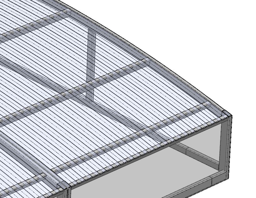
I want to carry out a numerical simulation on a load-bearing structure made of rectangular tubes covered with bent corrugated iron. In reality, this sheet metal rests on the entire framework and adds great rigidity to the structure. In the theoretical model, I am unable to attach it to the beams that support these sheets. I'm on Solidwork 2023 Sp5 in premium version, so with the basic finite element module.
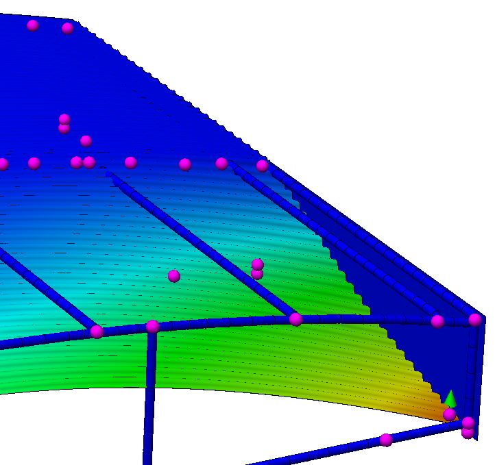
Surprisingly I have a contact between the sheet metal and half of my structure, but the rest of the sheet metal is not attached to the beams and therefore not supported...
In this case, I wouldn't use the " Beam " mode on all the profiles to be able to apply more realistic interactions between components. Also think about " combining " your mechanically welded machines to limit calculations
you can also save the assembly as a part for the Simulation.
But I would still like to understand why one of the sheets is well attached to my bent beams and the other one is not! There is still a mystery there^^
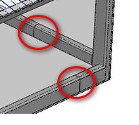
The nodes added are voluntary and necessary for certain load cases.
It is indeed a multibody part, even if a simulation study makes no difference between a part and an assembly.
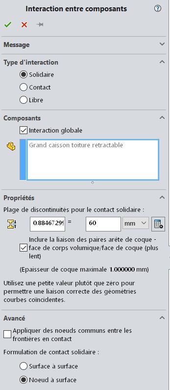
The addition of local interactions between beam and corrugated sheet with a slightly higher discontinuity range than the default, allowed me to run the model.