Hello
For future tests, I would like to be able to balance my drill with a tooth...
Is there a solution available in SolidWorks or is there an alternative to my problem?
Thank you 
Hello
For future tests, I would like to be able to balance my drill with a tooth...
Is there a solution available in SolidWorks or is there an alternative to my problem?
Thank you
Hello @ygoyard
Happy to welcome you to the forum. 
I hope that we can help you solve some problems, but also that we can benefit from your knowledge and experience.
For your question, this is not possible in a basic way nor in my humble opinion even with the PRO simulation module which allows you to do dynamics, vibration simulations and all the rest!
However, you should probably reformulate your needs because something is bothering me so that I understand you well.
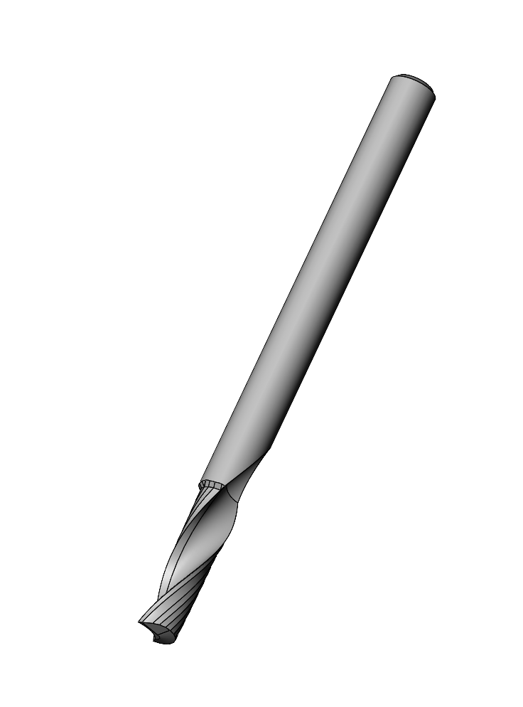
If I understand your problem, you have a bur tooth which obviously if it is rotated very quickly will eventually cause vibrations. (it all depends on the quality of the spindle).
So to be balanced, you have to put a mass on the other side of the axis of rotation.
With Solidworks it is easy to know the mass of the tooth as well as its CG.
So all you have to do is create a mass that will allow you to balance.
This mass cannot be in the same position as the tooth or have the same shape, otherwise it would be a two-tooth bur or there would be a collision.
So create a slightly larger (heavier) object that you will place inside the tooth support.
here again you can define any object by knowing the position of its CG in relation to the axis of rotation.
Then you put your tooth and balance mass in an ASM, then by looking at the CG of this ASM you see if it is perfectly in line or not.
Kind regards
Thank you, for the answer
I'm going to watch for all this by trying to modify my drill a tooth.
After for more detail, it would be more of the removal of material.
The fact that the tool has only one flute unbalances it and reduces the service life and surface finish on large side surfaces.
Kind regards
Yoh,
Hi @ygoyard Welcome to the forum ![]()
In order to complete the message of @Zozo_mp, I also think that you have to see if your cutter is balanced by going through the center of gravity. I use one method but there may be others (if you have any tips dear community ![]() )
)
To create a CG you need to add it in Evaluate/Mass Properties and you select your part(s) (don't forget to have a material in your part(s) for the result). Then you check " Create Mass Center Function". You close the window and your CG is displayed in the construction tree (under the name of Center of Mass).
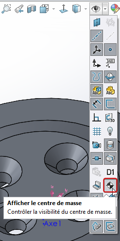
To display it on your piece, the viewing button must be activated:
Then, you add the axis of your target CG (your machine axis)
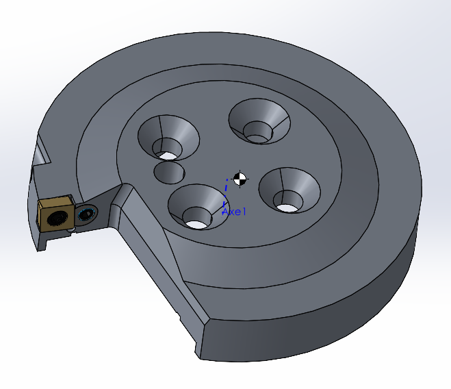
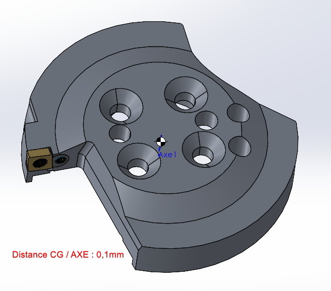
I found a special strawberry on the net but this is for example:
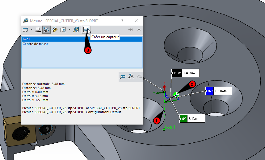
As soon as you have the CG and the axis, you can add a sensor. It will allow you to measure the distance between your CG and your axis automatically. To do this, you go to Evaluate/Measure. You select your CG and your axis. Then you click on " Create a sensor ":
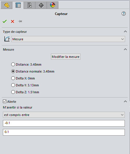
You check " Normal distance" (not mandatory but you can add an alert with a margin like in my example):
Now that the sensor is created, this is the most interesting part. ![]()
Your sensor is visible in the construction bar in the " sensor " folder:
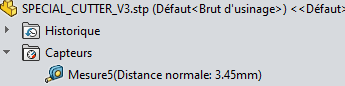
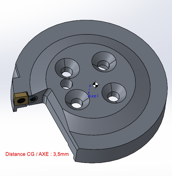
You will be able to work with the shape of your choice (holes and material removal in my example) in order to find a value equal to 0. Normally the sensor value updates, if it doesn't feel free to rebuild with the green ![]() light.
light.
Here is my result after 2 minutes of trial and error:
++ Nicolas
Bravo @Nicolas74
Especially after the second frame. 

But of course! the sensor! The sensor
Kind regards
Hello @ygoyard ,
This @Nicolas74 approach based on a sensor...
However, it is necessary to make sure that the machining intended to balance the cutter is carried out in the right place, since there are an infinite number of shapes and machining positions to place the CdG on the axis.
In the case of Nicolas74's disc-shaped cutter, this " static " balancing alone could give a fairly satisfactory result.
Is this the general shape of your strawberry?
Can you at least share an image of it?
To be complete: in addition to the " static " condition (CdG located on the axis), there is a condition on the inertia matrix of the rotating assembly, which is more difficult to characterize (dynamic balancing). This explains why it usually takes two additional masses, or two material removals, to ensure the proper balancing of an electric motor wheel or rotor.
A specific application is needed to simulate the dynamic behavior and provide a balancing solution. Maybe with the SolidWorks Motion module...
Or better, to have a tool balancing machine in the workshop.
Kind regards.
Hello @m.blt,
Thank you for these answers ![]()
Kind regards
Yoh.
It is apparently a small diameter cutter. The mass removed by the flute is rather modest, as is the corresponding offset of the CdG, at most a few 1/10th of a mm...
Why is balancing important? A dynamic simulation would give an idea of the forces generated in the spindle guidance.
And why not use a cutter with two or three teeth, the axial symmetry naturally ensures balance?
Hello,@m.blt,
No, these strawberries can reach Ø12.00 or even Ø14.00.
Balancing the tools is used to make a good surface finish as well as to preserve the spindle.
The one-tooth cutter is a special geometry that provides advantages on the machining of certain materials.