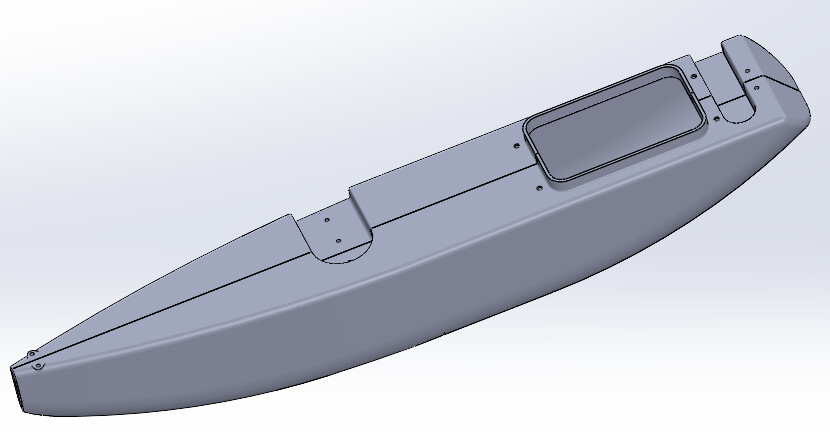
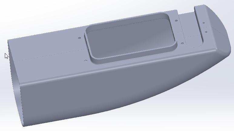
Hello everyone. I am currently creating a radio-controlled trimaran hull. I have 2 half shells cut in the center by the length. I assembled the 2 parts and I recorded it in . SLDPRT. Depending on the type of display style type, the connection between the 2 parts is visible or not. Question: When printing, will the link line be visible or not? Thank you
I would have imagined you working on a longship rather
For printing, what you see on the screen will be visible on the paper. So in line mode the lines will be visible and so will your demarcation.
On the other hand, for a weld I would chamfer the edges to be welded, for a better weld (depends on the type of weld). Which would at the same time make the demarcation visible even without the line display mode.
Hello Sylk. It is a 50 cm radio-controlled sailboat... Made of plastic. The question I ask myself is: from the .sldprt I will create a Step file, to print the parts.will the joining line of the 2 half shells be visible?
Hello @Scofield as he was talking about the display style, I thought he was talking about paper printing... but you put me in doubt.
If he's talking about 3D printing (extrusion, to be exact) and the spacing between the edges is 0 then it's not even that the slicer neglects it, it's that for him it's simply the same face, so 0 visible seams. If the spacing is greater than 0, it will seek to separate the edges. However, there is a setting in the slicer to define the max spacing to be considered as the same face, therefore to be closed: " Closing radius ".
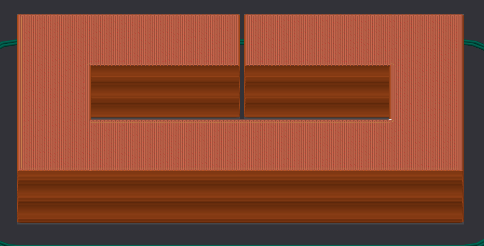
Coin with a deviation of 0.5:
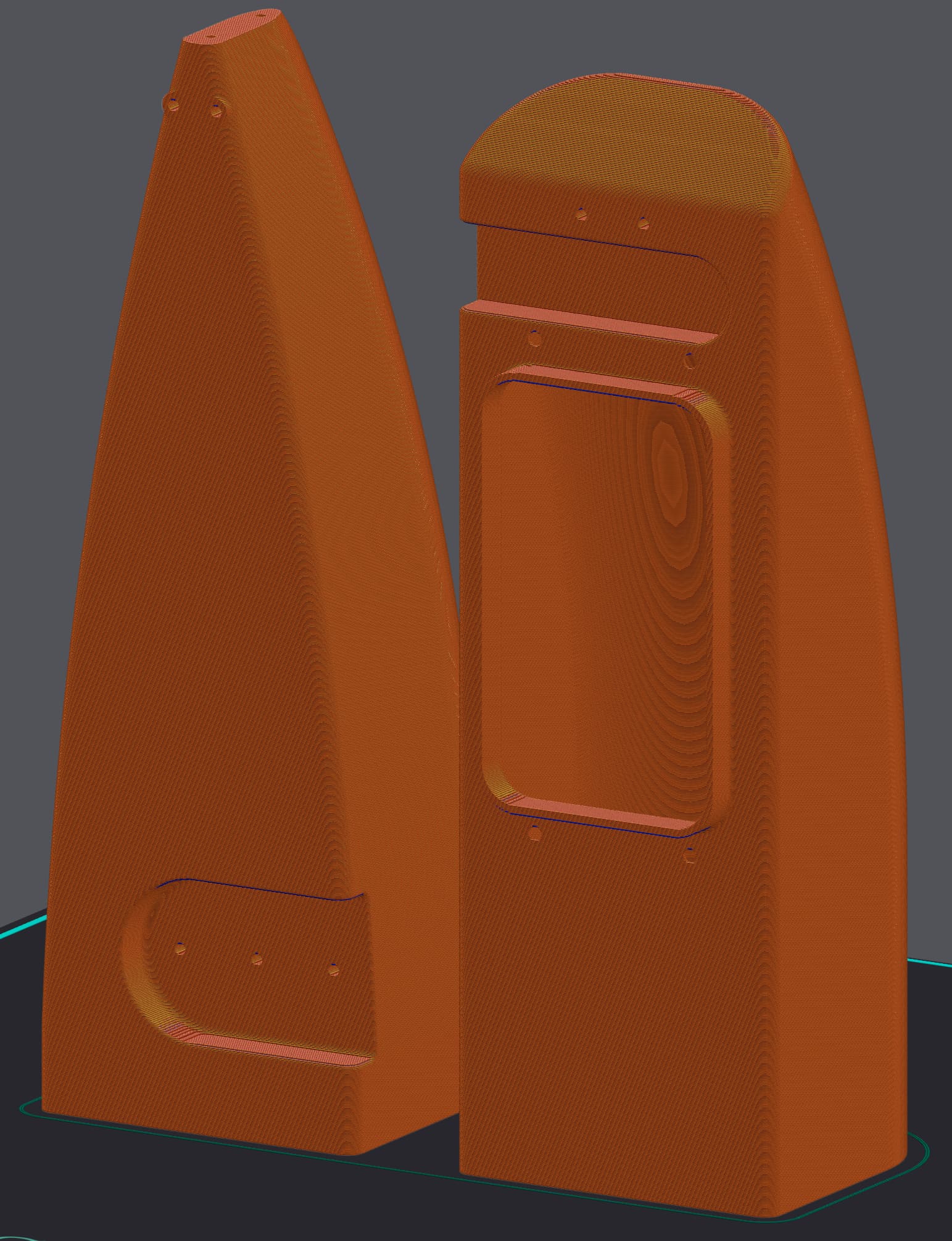
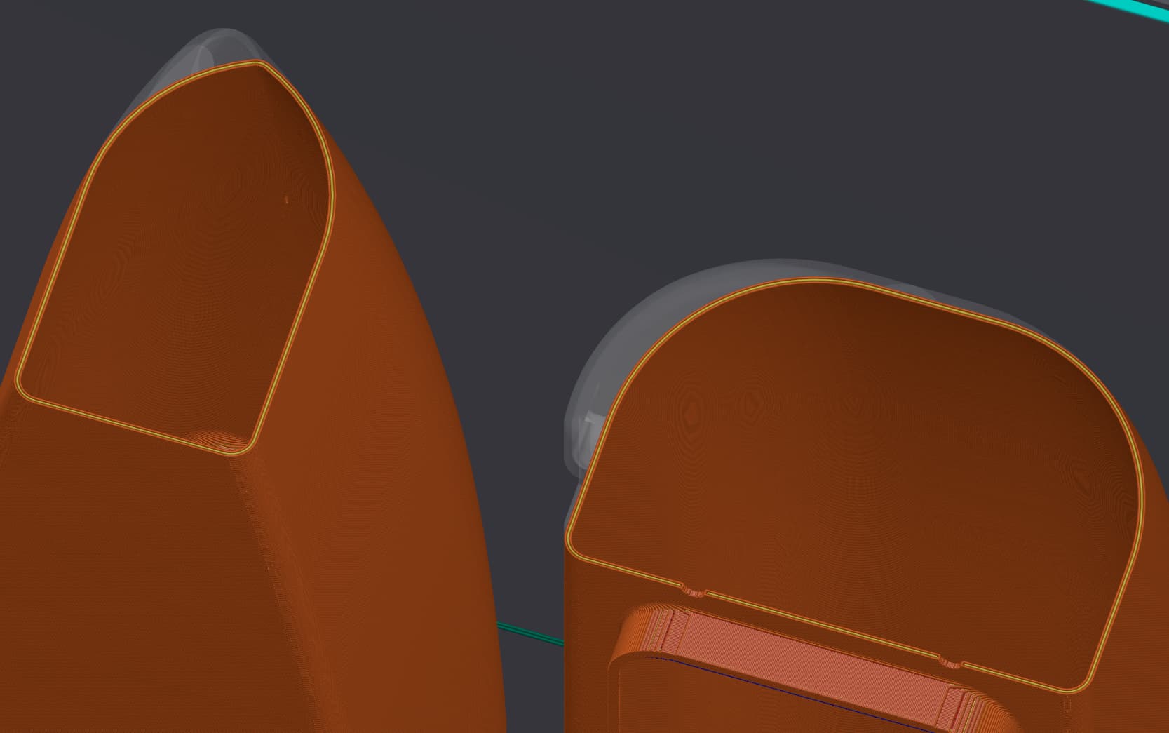
Sliced part with a smaller closing radius out of the way:
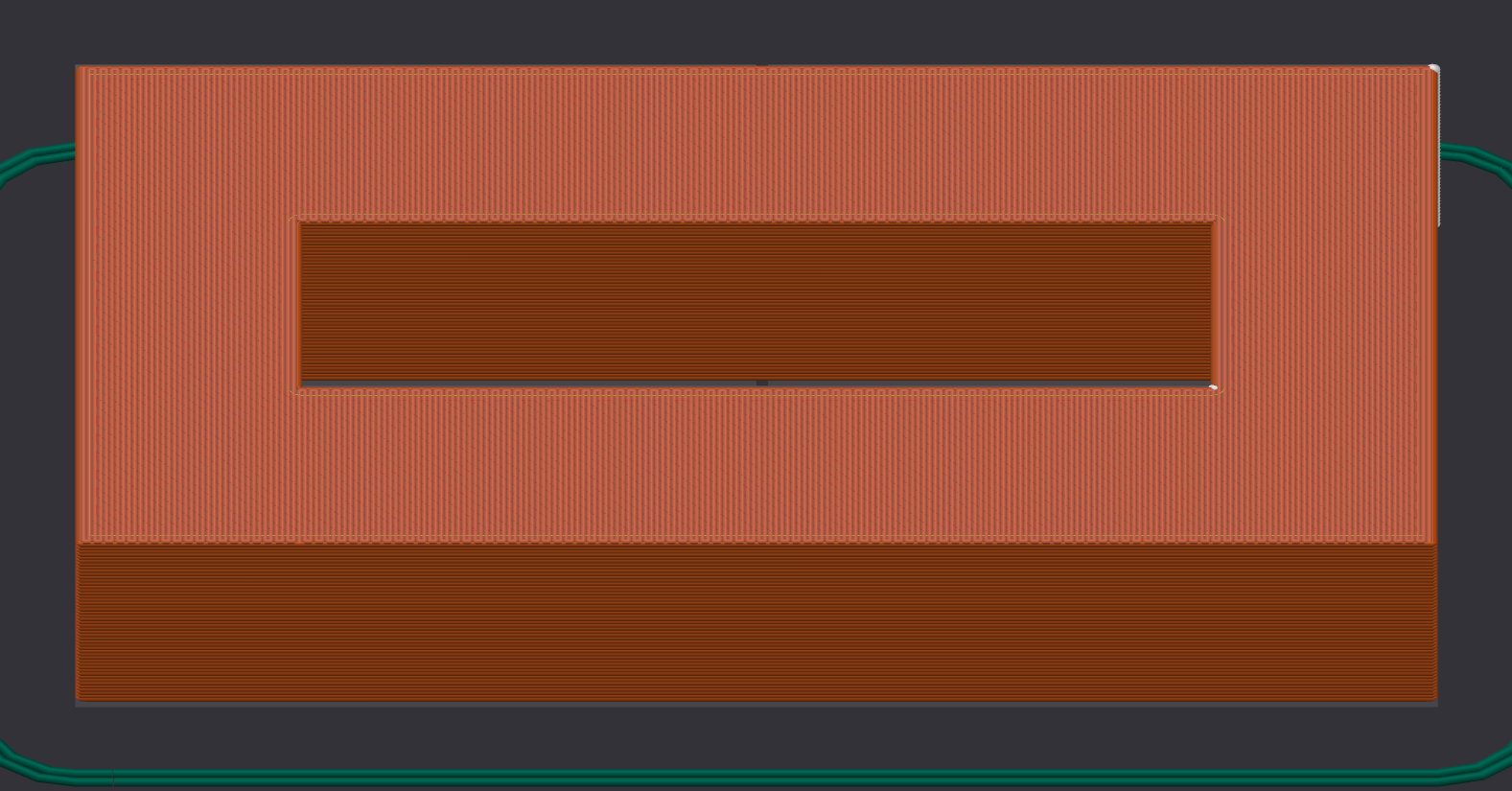
Sliced part with a closing radius greater than or equal to the gap:
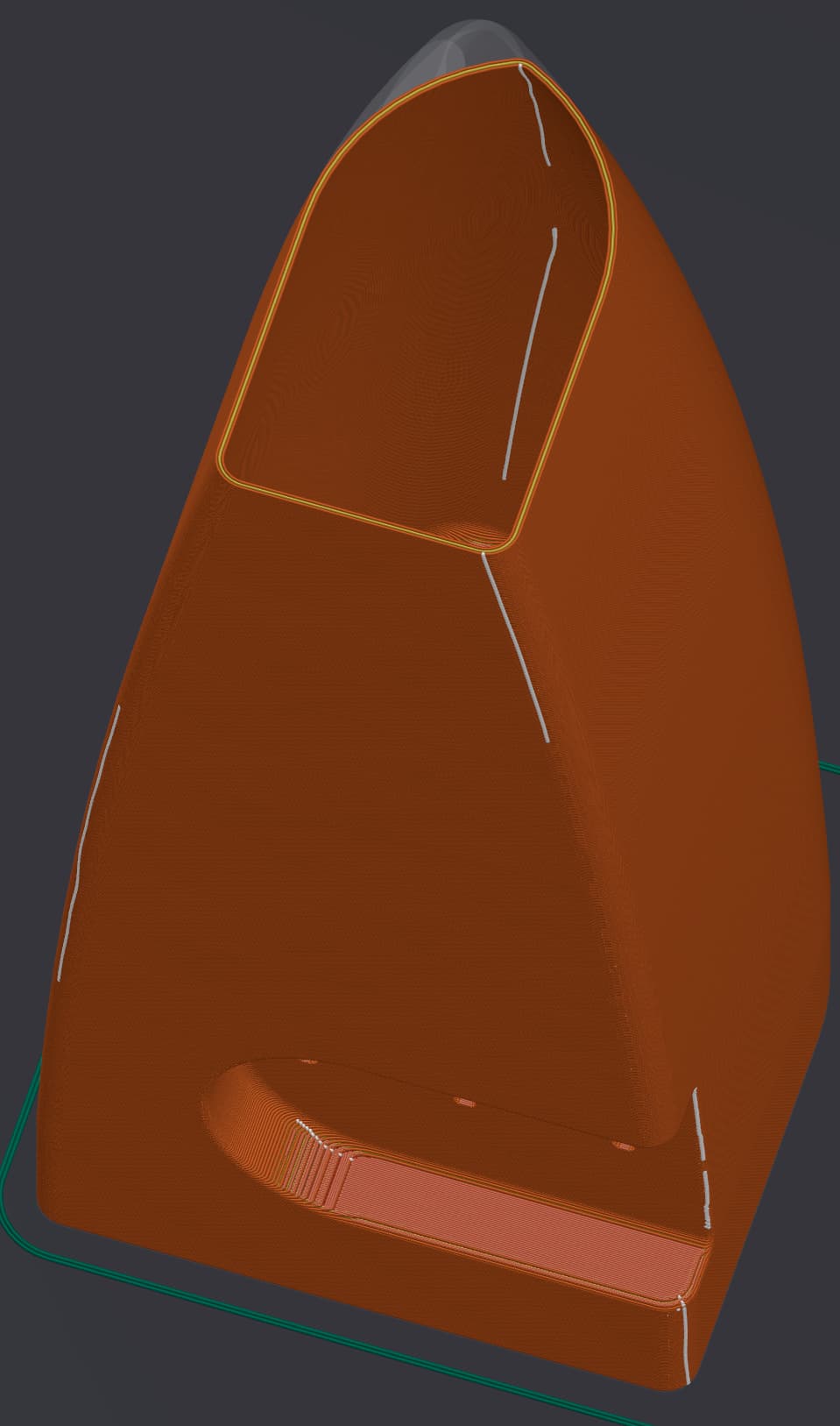
On the other hand, depending on the type of 3D printing (FDM on my images) you will have to manage seams (in white) that you can position where you prefer:
I've been doing 3D printing for 6 years. More than 50 reels sold. Maybe 8 kilos of PLA, everything else in PETG, ABS, ASA, etc... Always in nozzle 0.4. Layers? Varies according to project.
The rendering of PETG for this float is more than enough. It's a material that lends itself very well to this use, and I wasn't saying not to use it but simply that sanding is not a good idea (well except to paint or varnish the part it can help with the adhesion but a primer can be enough). It is better to use a blade. If the seams are too unsightly, shaving them closely will give a better result. That being said, with the right settings, there is a way to make them clean enough not to require post-processing.
3000h?! That's a lot. Mine shows 5h with a 0.4 nozzle and layers of 0.3 at an average speed of 200mm/s. 7h with the supports. And even then, I didn't even try to optimize the print settings for this model.
It sands well if you do it well. By taking his time. Because I plan to put on a primer and paint. On a sanded surface, primers and paint hold much better. Even in layers of 0.12, some rays are less smooth than the rest. We need to retouch. Some friends do this in PLA. Not for me. As for the 0.3 layers, even in TPU I don't do. Too rude! I close the debate here, which is a departure from the main topic of Solidwors. Thank you and have a good week everyone.