Hello
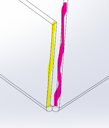
On a part made of sheet metal, I want to represent the weld seams (see image below: weld between yellow and red sides).
How should I do it.
Thank you.
Cdt

Hello
On a part made of sheet metal, I want to represent the weld seams (see image below: weld between yellow and red sides).
How should I do it.
Thank you.
Cdt

Hello
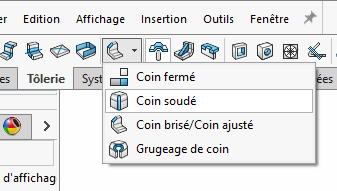
With the " welded corner" tool

Hello @stefbeno ,
thank you for your answer,
The problem with this solution is that you have to make 2 drawings with different references, because after having made "welded corner" the unfolded of my sheet metal part is no longer done!
Hello,
for my part the part unfolds with the corners welded
Rep 2 - Sharing and infinite knowledge. SLDPRT (2.9 MB)
Hello
Strange, the solution provided by my classmates is the right one. There's something wrong somewhere!!
Hello, unless I'm mistaken, the soldered corner function must be the last one of the arbo. If there are sheet metal functions after the part is no longer foldable (vague memory on SW2020)
Indeed, and in fact the functions are grayed out after performing this operation
In 1st the 4 plies Sheet bent on edge2 then the 4 crushed plies Crushed plie3 and finally the 4 Sheet metal bent on edge1 with an extended tool
In fact, where it gets stuck with the welded corners, those are the drawings.
one sheet the folded model and a second sheet the unfolded model
at home it's good
Rep 2 - Sharing and infinite knowledge. SLDDRW (1.2 MB)
Rep 2 - Sharing and infinite knowledge. SLDPRT (6.2 MB)
Hello;
The flatpattern is a configuration on which it is possible (recommended) to "Remove/configure" the "Welded Corner" functions.
Normally these functions deactivate themselves when they are flattened, unless they are created after the fact, in which case they have to be configured with the manual.
Kind regards.
PS: Happy Niversary @Cyril.f 
I don't know about you guys but I find that he still makes himself thirsty (@Cyril.f a happy one )
)


