I'm drawing an optical filter in SolidWorks 2023. It is a simple cylinder of Ø20mm and 1mm thick. In terms of 3D modeling, it's fine. I get by.
On the other hand, in terms of the drawing, I'm drying
In optics, it is customary to tolerate the parallelism between the two faces in arcminute.
In mechanics, a parallelism of X defines a tolerance zone between two planes distant from Xmm. So not an angle.
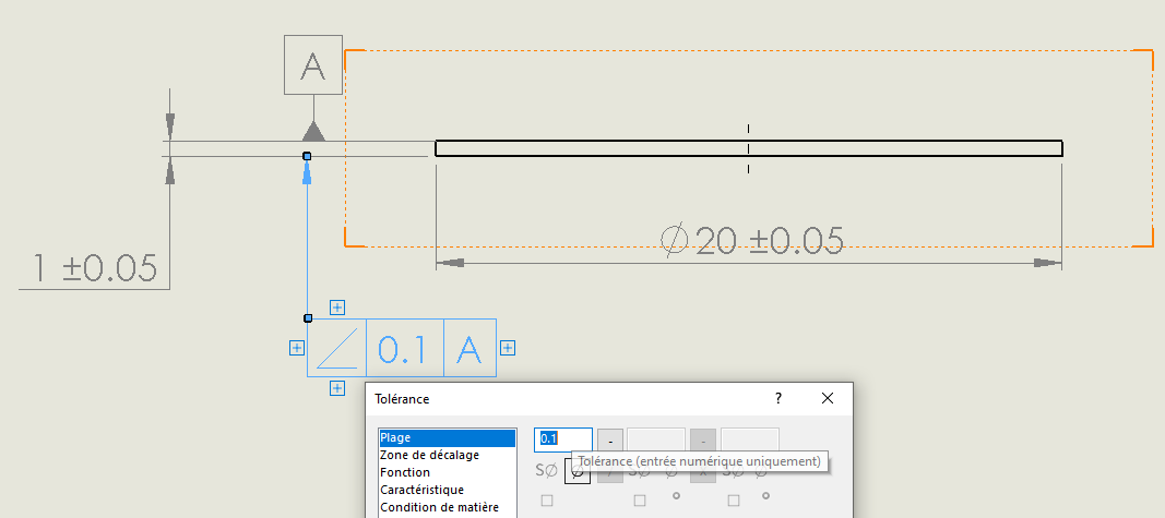
I can use an angular tolerance, but the geometric tolerance framework doesn't allow me to put anything other than numbers in the range.
Is there a way to display/change the unit within the range of a geometric tolerance and override this " numeric input only " rule? In this case, I would just like to add a '
It seems to me that this limitation has been raised several times. It will be answered with SW 2026 with which it will be possible to add symbols in the geometric tolerance framework.
It is indeed just possible to enter just numerical values. By clicking on the + symbol you can add annotations that are not framed but that will be associated with the geometric tolerance. Why not put a location in relation to A?
Tolerance zone = two parallel planes separated by a value t. The face (or midplane) should remain in this area.
And as a stupid question... but you have to work according to a standard that is recalled on your MEP. It doesn't specify your work units? Maybe that's more than enough?
@Silver_Surfer : Do you have a link with the future developments brought by the SW 2026?
@Sylk : It would be possible on a dimensional dimension, but unfortunately not in a geometric tolerance framework
@coin37coin : That's the problem, optical manufacturers are not mechanics, and they express parallelism in arcmin. In desperation, I did add a footnote to indicate the parallelism, but I was looking for a more " ISO " way to indicate it on the map.
In short, while waiting for SW2026, I only have the block or footnote solution left.
Note: SW now includes new features in each SP (I'm not a fan of this method: we don't have a really stable SP anymore), so this list will grow with each SP release.