Bonjour à tous,
Je vérifie au calcul une échelle à crinoline qui équipe une passerelle de maintenance amovible. Cette échelle est en 2 parties car la partie basse doit pouvoir être enlevée lorsque l’on stocke cette passerelle au sol. L’échelle est donc composée :
- d’une partie fixe en acier soudée sur la passerelle avec une crinoline et un portillon d’accès
- d’une partie amovible qui est une échelle aluminium du commerce et dont les 2 premiers barreaux du haut viennent se loger dans des crochets prévus sur la partie fixe
L’objectif est donc de vérifier :
- L’échelle amovible alu du fait de son utilisation non conventionnelle (supportage via les barreaux)
- L’échelle fixe, notamment la partie avec les crochets de supportage
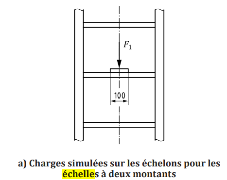
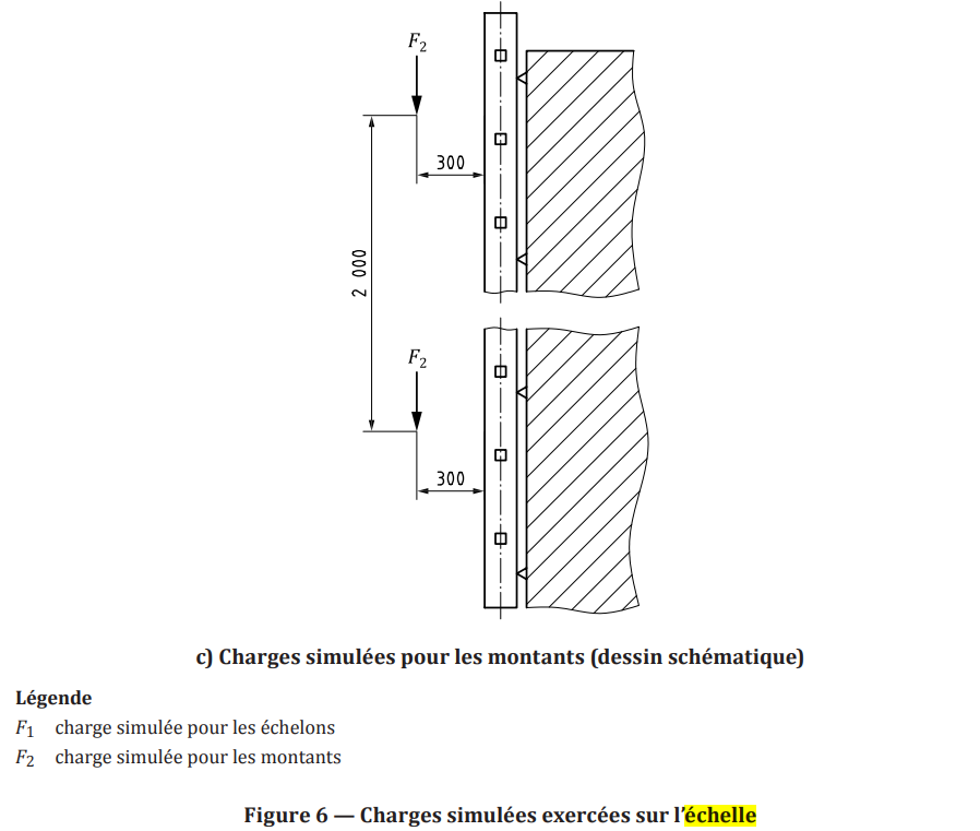
Pour les cas de charge, je me base sur la norme ISO 14122-4 mais j’ai un peu de mal à interpréter les charges simulées qui y sont présentées ; on a :
- Une charge F1 appliquée sur un barreaux sur une largeur de 100mm qui logiquement correspond à la charge d’un utilisateur via un de ses pieds appuyé sur le barreau (valeur norme 1.5KN)
- Une charge F2 qui semble modéliser la charge d’un utilisateur se retenant sur les montants (valeur norme 1.5KN) ; c’est une charge déportée mais dont la zone d’application n’est pas précisée (pour ma part j’ai considéré une zone de 100mm à l’arrière de chaque montant et à l’horizontale de F2 qui correspond aux mains de l’utilisateur…)
J’ai un peu de mal a voir si ces sollicitations doivent être appliquées simultanément ou chacune à part.
Simultanément : on applique 2 fois la charge de l’utilisateur ce qui est très surchargé pour le calcul
Séparément : pour F1 seul on peut considérer que l’utilisateur grimpe à l’échelle près des montants en se tenants aux barreaux et négliger F2 mais si l’on applique F2 seul ça revient à considérer que l’utilisateur se retient aux montants mais n’a aucun pied posé sur un barreau d’échelle…
Je ne sais pas trop si je me pose trop de questions ou si je fais complètement fausse route…
Est-ce que quelqu’un a une idée ?
En p.j. :
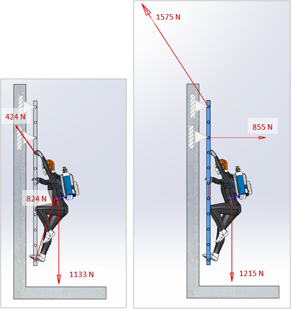
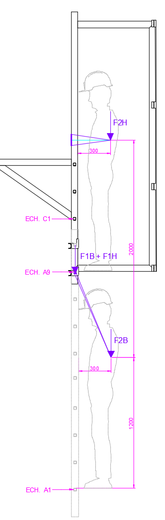
Un schéma des charges appliquées en simultané (F1 + F2) sur l’échelle fixe via les 2 crochets du bas. On prend le cas le plus défavorable avec 2 utilisateurs présents sur l’échelle alu :
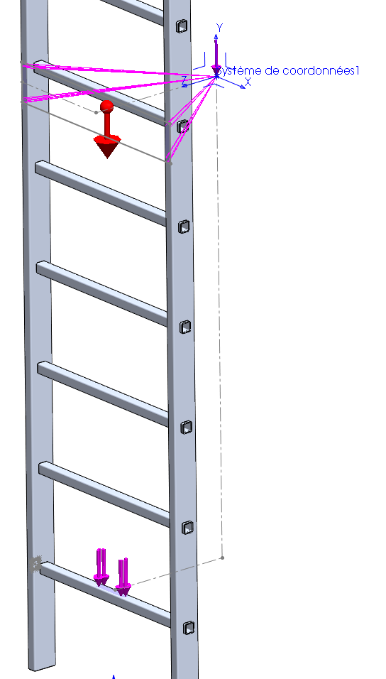
Une vue des charges appliquées pour la vérification de l’échelle alu cette fois :
Merci d’avance.