Bonjour,
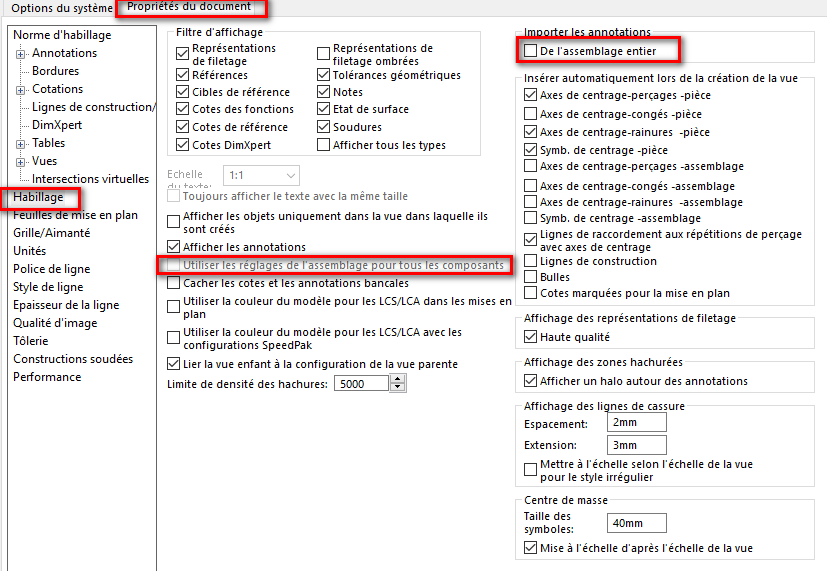
Depuis la passage à la version 2025 SP4 nous rencontrons un affichage intempestifs des points d’origines des pièces et assemblages.
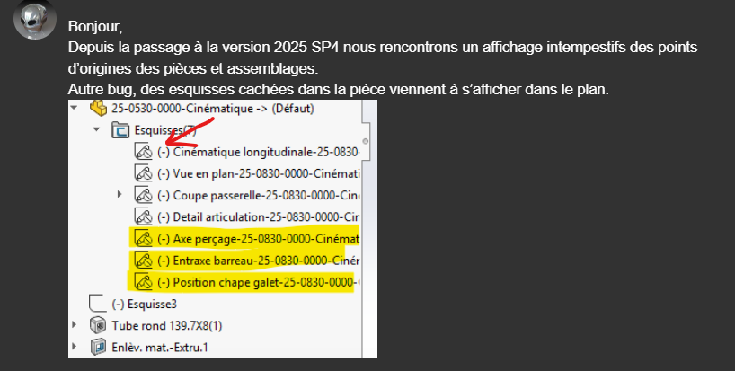
Autre bug, des esquisses cachées dans la pièce viennent à s’afficher dans le plan.
Au lieu d’apporter des solutions IA ce serait pas mieux de corriger ce genre de bug avant la version Sp04… Plus ça va plus les versions final sont également bogués, à croire que c’est fait exprès pour nous pousser à installer la version en ligne qui leur simplifiera la tâche au niveau des MAJ (1 seul version à entretenir…)
Pour ton Pb désolé mais encore en version 2023 SP5 (avec les bugs qu’elle comporte…)
Le coté « intempestif » m’intrigue quelque peu, mais, pour me faire une idée plus précise, @ronathan peux-tu poster des captures écran de l’état du « monter/cacher » sur une pièce, un assemblage et une mise en plan qui pose problème ?
exemple:
De mon côté j’ai exactement le même soucis, + tous ceux qui viennent s’ajouter.
L’ajout des nouvelles fonctionnalités polluent le code de base du logiciel, et puis ça s’accumule encore et encore, jusqu’à ce que ce dernier plante 4-5 fois par jour si ce n’est plus, et sans aucune raison (enregistrement, nouvelle esquisse, nouveau fichier, peu importe tout est visiblement sujet à créer un plantage)…
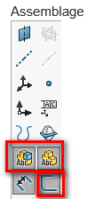
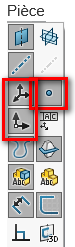
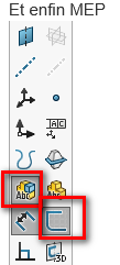
Alors, ce que j’interprète à partir des captures crans ci-dessus:
pour les assemblages:
L’affichage des « annotations de composants » est actif, celui des esquisses aussi
de même pour celui des « annotations de premier niveau »…
pour les pièces:
L’affichage des points, des origines, des axes, des plans et des systèmes de coordonnées sont actifs.
Pour les mises en plans:
L’affichage des esquisses est actif ainsi que celui des « annotations de premier niveau »…
Avec ces information je me dis que si, par exemple, une Origine est réglée sur « Visible » dans une pièce (Dans l’arbre de construction), elle apparaitra dans l’assemblage (« annotations de composants ») et si dans la mise en plan « annotations de premier niveau » est actif, dans ce cas les chances pour que cette Origine issue de la pièce soit aussi visible est proche de 100%.
Et c’est aussi le cas pour les esquisses…
En conclusion, je pense que ce n’est qu’une question de réglage de la visibilité des élément (Dans Monter/Cacher) qui est en cause en non un problème inhérent à la version de Solidworks. (Et ce n’est pas mon type de discours habituel… ).
Le truc c’est que sur d’anciennes conception issu de la version 2023 je n’ai pas ce problème.
De plus auparavant je n’avais pas à jouer avec les affichages d’esquisse dans la mise en plan étant donné qu’elle était caché dans l’assemblage et dans la pièce.
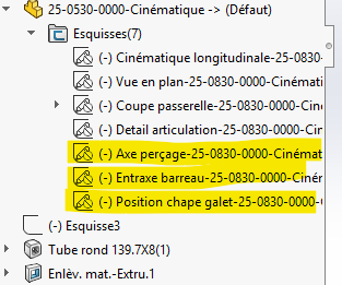
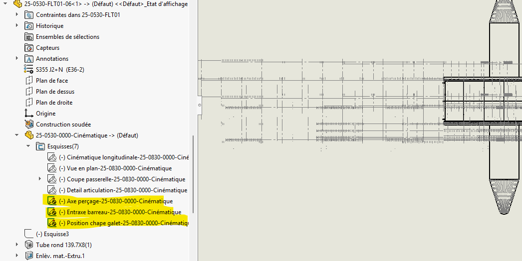
Mes deux premières captures montrent bien que les esquisses sont non visible dans ma pièce et visible dans la MEP.
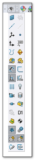
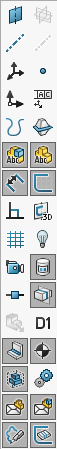
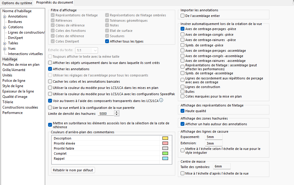
Ici la capture est issue de Solidworks 2022 et cela ne m’étonnerai qu’à moitié que la version 2025 soit pourvue d’autres options…
J’ai encadré en rouge quelques options qui, déjà à l’époque, peuvent provoquer des artéfacts non désirés sur les Mises en plan…
Oui c’est bien une fonction insérer pièce.
Technique que j’utilise depuis un bon moment sans problème, depuis la 2025 PAFFF!
Et de plus c’est aléatoire, je m’explique sur certaine pièce tout beigne et avec d’autre les esquisse s’affiche dans la MEP. Autres bizarreries le faite de faire une vue projetée cache les esquisses de la vue principale pour les afficher dans la vue projeté.
Seule solution est donc de décocher la visibilité des esquisse dans mon modèle de MEP. C’est pénible car très utile pour récupérer des tracés ou schémas de conception.
On a des sous-traitant qui l’utilise, on a eu et on a encore des problèmes de mise à jour pour ne citer que celle-ci.
Pour information nous avons remarqué un problème sur l’édition d’une fonction utilisant des esquisses importées, dans les fonctions d’extrusions.
Lors de l’édition de la fonction l’esquisse est accessible et peut être bougé sans contraintes ni cotes. Est-ce toujours le cas sur 2025 ? Nous sommes en 2022.
Bon courage la fonction quoique ancienne n’est pas abouti, je trouve. Mais si tu me confirmes la correction du Bug cité ci-dessus, je t’en remercie d’avance
Bonjour,
c’est effectivement le cas pour les esquisses dérivé, on peut les bouger par erreur en simple glisser/déposer.
En revanche en utilisant la fonction insérer pièce c’est plutôt pas mal.
Ca a l’avantage d’avoir une esquisse maitresse que l’on modifie et qui pilote tout le reste.
Je fonction pareil la méthode dite squelette, cela concentre les informations sur une seul pièce qui peut être piloté par une famille de pièce et une feuille Excel extérieur. Méthode que j’approuve complètement gain de temps, et sécurise les conceptions douteuses empiriques.
Pour solutionner le problème d’esquisse, je te conseille de créer un plan via les esquisses de ton squelette normale à la direction de ton esquisse. A l’aide de ce plan tu créais une esquisse et tu projettes ton esquisse dessus. Problème résolut ou contourné
Fonction que je trouve non abouti, en comparaison avec inventor qui utilise cette méthode mais en gerant l’import de maniere fiable et efficace.
Oui c’est un des problèmes que l’on rencontre.
Dès que tu bouges un élément c’est définitif pour le mettre à jour avec un retour à son état initial. il faut crée un élément dans l’esquisse du squelette, et mettre à jour le squelette intégré dans la pièce. La looze.
Et les mise à jour son lourde !!!
Il y a possibilité de la contraindre, mais il faut ruser :
Créer une extrusion à partir de l’esquisse importé.
Valider puis rééditer la fonction d’extrusion : c’est à ce moment là que l’esquisse peut être bouger, mais il est également possible de lui ajouter une relation pour la contraindre en place.
Attention, il n’est plus possible de supprimer cette relation une fois ajoutée. C’est pourquoi il préférable selon moi de la contraindre par rapport à l’origine.
Je m’étais posé la question des possibilités lors de l’Edition de la fonction, et donc de mettre des côtes. Mais c’est deux fois le boulot, une fois dans l’esquisse du squelette, et une fois dans la pièce qui accueille le squelette. Mais que se passe-t-il quand tu fais une mise à jour de cote ?? il doit y avoir de la casse …
Si tu te sers de l’esquisse du squelette, pour poser un plan, et créer une esquisse. Tu projettes les entités d’esquisse du squelette, le bug n’existe plus. Essai !
Nous réalisons des ponts de levage des milliers de pièces utilisant le même squelette. Si nous devions recontraindre les esquisses à chaque fois se serait un problème je pense.
Ce bug est flippant, je ne comprends pas qu’il ne soit pas résolu. Dassault a d’autre chat à fouetter
D’autre solution existe mais ce n’est pas le sujet présent ici