Hallo, ich brauche Ihre Hilfe.
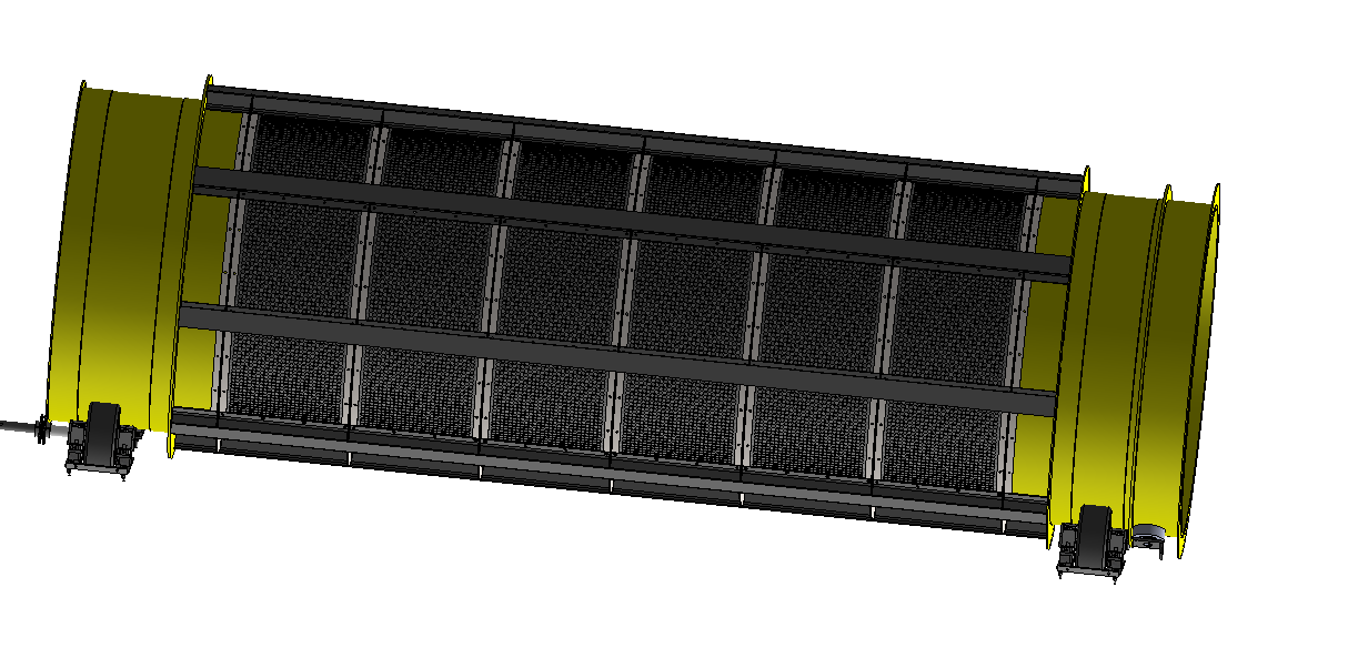
Ich habe ein 16-Tonnen-Rohr für einen Ø2500 mm, das um 3° geneigt ist und eine Drehung von 50 U/min hat.
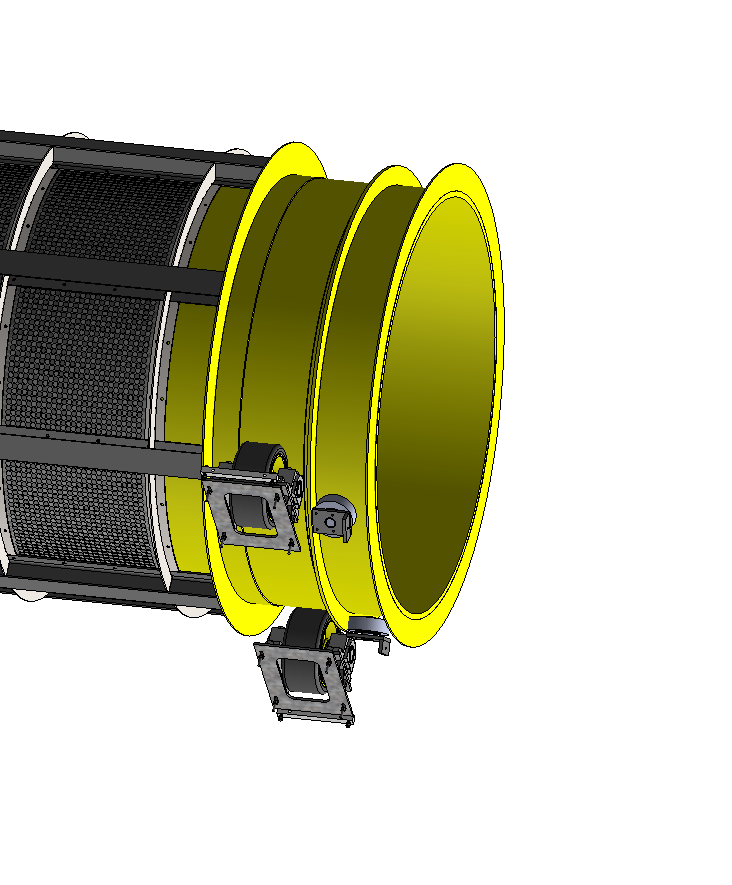
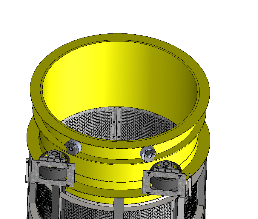
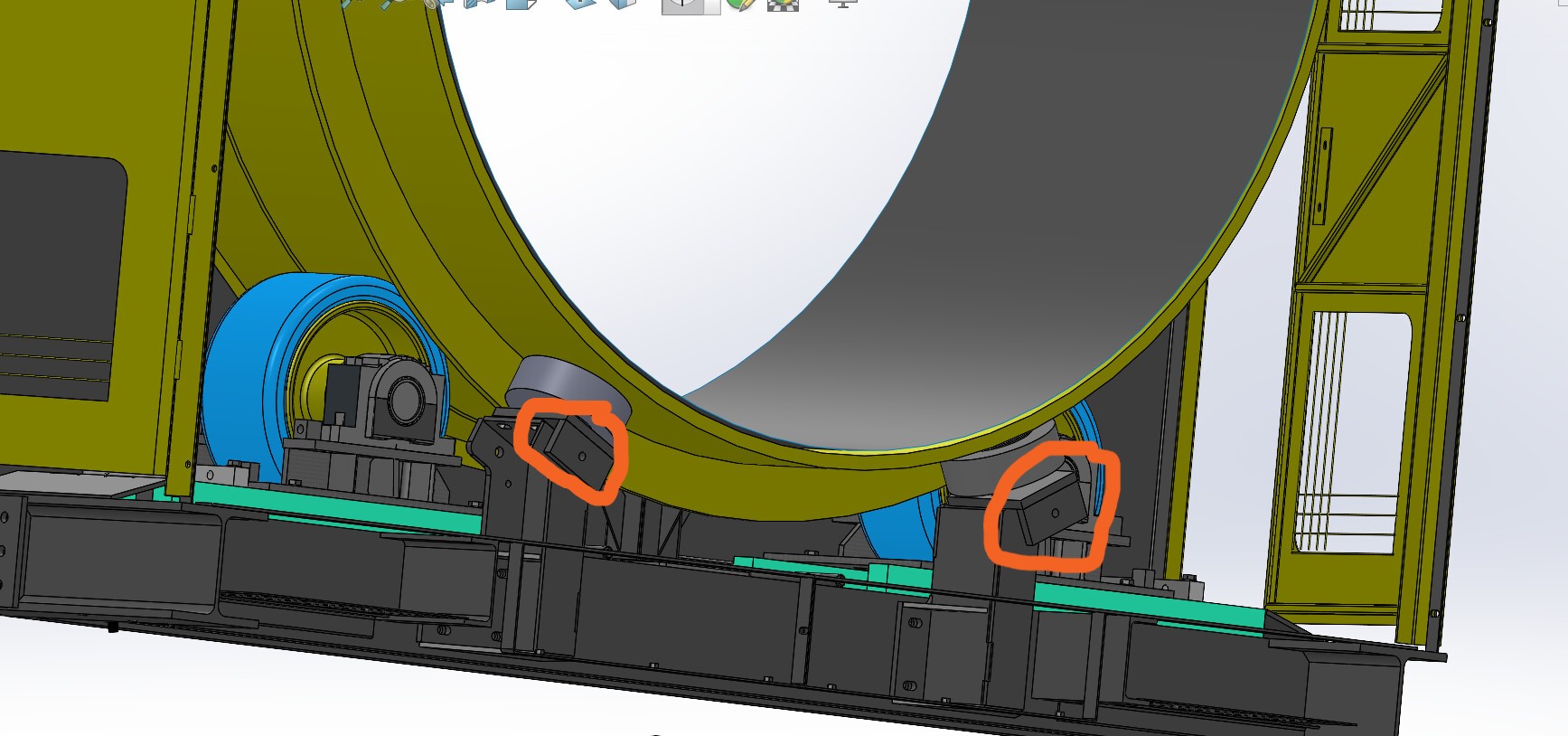
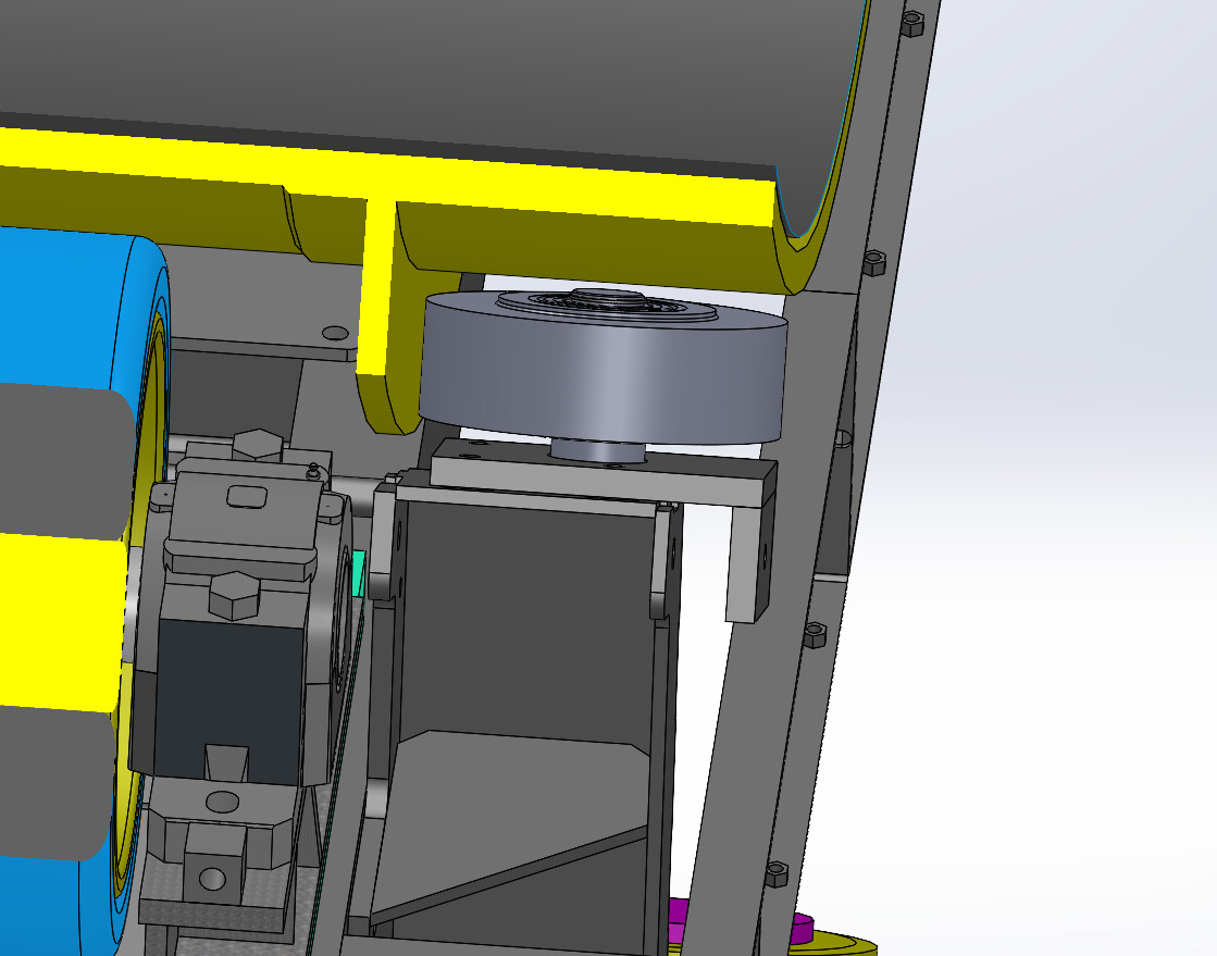
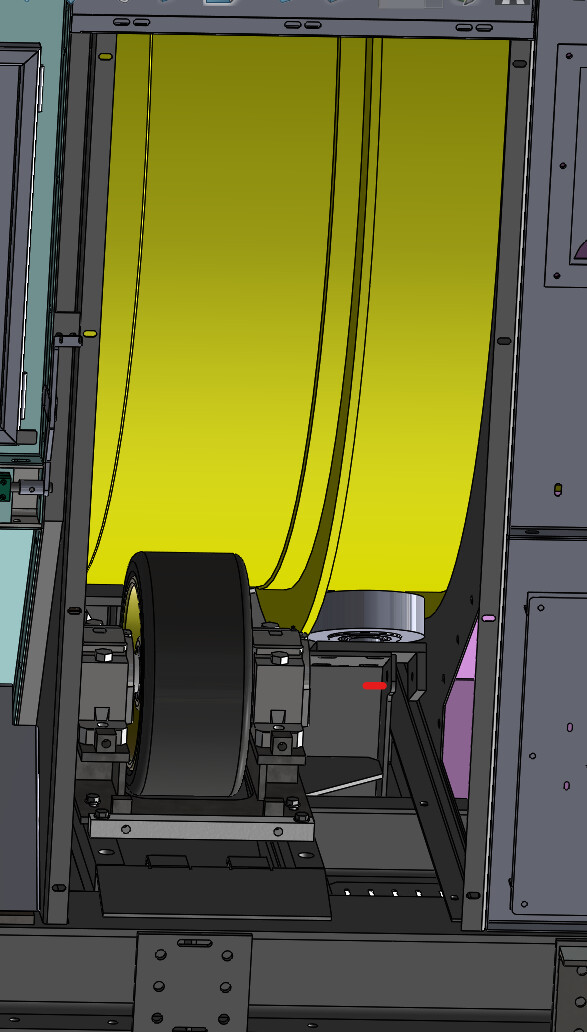
Ich muss eine Halterolle am Ende des Rohres platzieren, um seine Translation aufgrund seiner Bewegung und der Schwerkraft zu blockieren
Ich habe 2 Fragen.
1= Wie groß ist die Kraft am Ende des Rohres für eine Rolle in der Mitte.
2= Wie hoch ist die Kraft am Ende des Rohres für 2 Rollen im Abstand von 50°.
Danke für Ihre Hilfe
Wie wird es gedreht angetrieben? Motorisierte Walzen wie z.B. ein Wender?
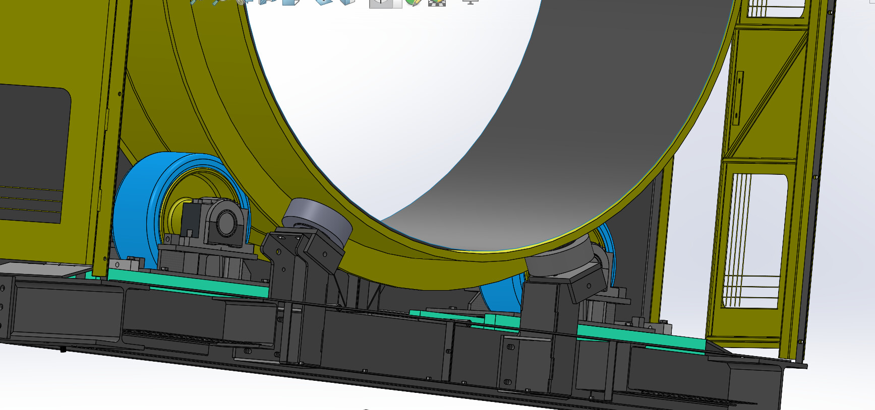
Das Rohr ist auf 4 Rädern platziert, von denen eines motorisiert ist.
Hallo;
Gewicht (P): P = m * g = 16000 kg * 9,81 m/s² = 156960 N
Die Komponente des Gewichts parallel zur schiefen Ebene: F = P * sin(3°) = 156960 N * 0.0523 = 8209 N
Für eine einzelne Rolle, die in der Mitte des Rohrs platziert ist, entspricht ihre Haltekraft der Komponente des Gewichts parallel zur schiefen Ebene:
Kraft für einen Kieselstein = = 8209 N
Bei zwei Rollen im Abstand von 50° wird die Kraft zwischen den beiden Kontaktpunkten verteilt. Wir können die Formel für die resultierenden Kräfte verwenden, um die Kraft auf jede Rolle zu berechnen:
F_retenue_2 = F / (2 * cos(25°))
F_retenue_2 = 8209 / (2 * 0,9063) = 4528 N pro Rolle
Die Gesamthaltekraft beträgt daher 4528 N * 2 = 9056 N und ist damit aufgrund der Kräfteverteilung etwas höher als bei der Konfiguration mit einer einzelnen Rolle.
=> Ich würde die Notwendigkeit hinzufügen, diesen Rollen einen Sicherheitsfaktor hinzuzufügen, um die Zentrifugalkräfte auszugleichen, die durch die Drehung des Rohrs erzeugt werden...
Ohne Kenntnis der beteiligten Materialien ist es nicht einfach, die Reibungskräfte zu berechnen.
4 „Gefällt mir“
Vielen Dank.
Hier ist die Referenz des verwendeten Kieselsteins
Polyamid-Walze GSPO 252/50K Last 6000 daN
1 „Gefällt mir“
BLICKLE ist ein guter Lieferant, Qualitätsprodukte.
Kein Kommentar zum gewählten Modell.
Auf der anderen Seite, wenn ich das sagen darf, hätte ich die Seite des Anschlags für die Einstellung der Position der Plattenrollen umgedreht, denn wenn man sie einmal eingestellt hat - da die Schubkräfte immer noch nicht zu vernachlässigen sind, kann es auch zu Vibrationen kommen (lineare Geschwindigkeit von 400 m/min) - wird es einfacher sein, kalibrierte Unterlegscheiben zwischen der Stütze und der Platte zu positionieren. Eine Garantie für Steifigkeit und Stabilität im Laufe der Zeit.
2 „Gefällt mir“
Vielen Dank für Ihren Vorschlag.
Aber es ist schwer, die Position zu wechseln, weil ich keinen Platz habe.
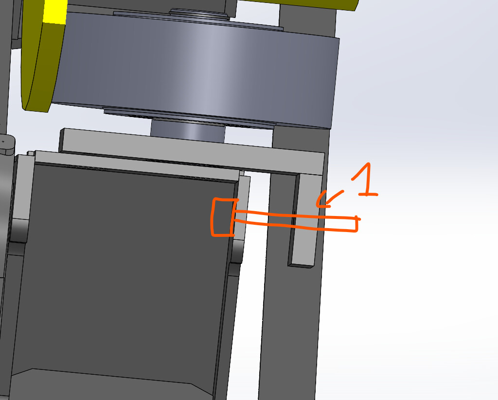
Die Rolle wird von unten fixiert

Die Einstellung erfolgt mit einer M20-Schraube, in dem Wissen, dass Sie in Rep1 angezapft sind.
1 „Gefällt mir“
pfffff Die dunkle Seite zeigt sich ![]()

4 „Gefällt mir“
Vielen Dank an alle Referenten für Ihre Teilnahme.
Möge die Macht mit euch sein.
1 „Gefällt mir“
Um die Kraft zu bestimmen, die durch Schwerkraft und Drehung auf das Rohrende ausgeübt wird, analysieren wir die Situation in zwei Konfigurationen:
Bereitgestellte Daten:
Rohrmasse: 16 Tonnen (16.000 kg)
Durchmesser: Ø2500 mm (R = 1250 mm)
Neigung: 3°
Rotationsgeschwindigkeit: 50 U/min (ω = 50 × 2π / 60 rad/s ≈ 5,24 rad/s)
Schwerkraft: g = 9,81 m/s²
Fall 1: 1 Kieselstein in der Mitte
Fall 2: 2 Kieselsteine im Abstand von 50°
- Berechnung der Kraft am Rohrende für 1 Rolle in der Mitte
Kraft aufgrund der Schwerkraft (Fg)
Durch die Schwerkraft entsteht ein Bauteil, das parallel zur schiefen Ebene verläuft und dazu neigt, das Rohr gleiten zu lassen:
F_g = m \cdot g \cdot \sin(3°)
Zentrifugalkraft (Fc)
Durch die Wirkung der Rotation wird eine Zentrifugalkraft auf den Schwerpunkt erzeugt:
F_c = m \cdot R \cdot \omega^2
All diese Kraft wird auf die einzelne Walze übertragen.
- Berechnung der Kraft für 2 Rollen im Abstand von 50°
Wenn es zwei Rollen gibt, wird die Kraft zwischen den beiden verteilt, abhängig von ihrer Position und der Richtung der Kräfte. Jeder Kieselstein erhält einen Teil der resultierenden Kraft.
Ich werde die Berechnungen für diese Kräfte durchführen und Ihnen die genauen Ergebnisse liefern.
1 „Gefällt mir“
Ergebnisse der Berechnungen:
-
Kraft durch die Schwerkraft (Fg): 8,21 kN
-
Zentrifugalkraft (Fc) : 548.31 kN
-
Gesamtkraft auf einer einzigen Rolle: 548,37 kN
-
Kraft auf jede Rolle (bei 2 Rollen im Abstand von 50°): 302,53 kN pro Rolle
Deshalb:
Wenn Sie nur 1 Rolle verwenden, muss sie ca. 548,37 kN tragen.
Wenn Sie 2 Rollen im Abstand von 50° verwenden, kann jede 302,53 kN tragen.
1 „Gefällt mir“
Hallo;
Ich hatte Zweifel, als ich Ihre Antwort las, und sei es nur, weil sie kein " Hallo: " hat, also ging ich zur Überprüfung:
Und auch auf:
https://quillbot.com/ai-content-detector
… Bitte zitieren Sie Ihre Quellen, wenn Sie eine KI verwenden... Nicht, dass sie alle schlecht wären, aber wir dürfen nie vergessen, dass sie jederzeit halluzinieren können... Ein bisschen wie der Mensch übrigens.
Ich denke, dass die Tatsache, dass der Hinweis auf die Verwendung einer Antwort durch I. A ist vor allem eine Frage der Ethik und des Respekts.
Und wenn ich jemals etwas falsch machen sollte, bitte ich um Entschuldigung.
@OBI_WAN : Ich habe nicht die Möglichkeit, die genannten Berechnungen zu überprüfen, vielleicht bin ich ja derjenige, der halluziniert... ![]()
5 „Gefällt mir“
Hallo @Maclane ,
In der Tat müssen wir uns vor KI in Acht nehmen.
Ich würde sagen, dass seine Antworten oft relevant sind, aber von der Präzision der gestellten Frage abhängen, die klar und vollständig formuliert sein muss.
Insbesondere enthält die Antwort von @maurizio eine Verwirrung, die nicht auf ChatGPT zurückzuführen ist: Im Falle der " Zentrifugalkraft " (Fc = m w² r) ist der zu berücksichtigende Radius r der Abstand von der Rotationsachse zum Schwerpunkt des Objekts und nicht der Radius R des Zylinders. Wir können davon ausgehen, dass dieser Abstand r sehr klein ist, wenn der Zylinder von geeigneter Qualität ist.
Darüber hinaus wirkt die " Zentrifugalkraft " radial und hat keinen Vorsprung in Richtung der Rohrachse.
Meiner Meinung nach ist diese Zentrifugalwirkung bei der Wahl der Rollen der Axialstütze völlig zu vernachlässigen.
Um auf das anfänglich gestellte Problem zurückzukommen - die Berechnung der Axialkraft zur Validierung der Rolle(n) - verdient die Tatsache, dass 2 Rollen verwendet werden, eine Überlegung. Lassen Sie mich das erklären:
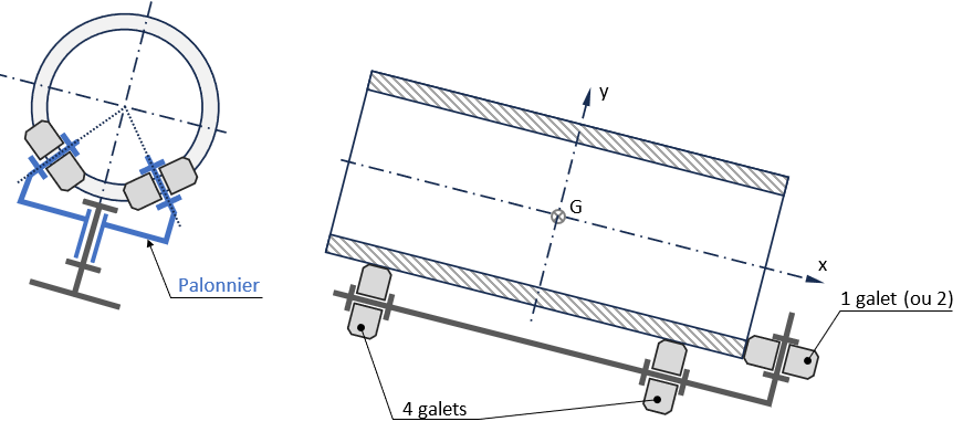
Kein Problem für die Drehführung des Rohres, die von 4 Rollen (eine davon motorisiert) übernommen wird, die die Drehachse definiert.
Es gibt jedoch keine Garantie dafür, dass die Rollen, die für den Axialanschlag verwendet werden, beide mit der Vorderseite des Rohrs in Kontakt kommen. Es hängt alles von der Qualität der Oberflächen ab, maschinell oder roh, von der Rechtwinkligkeit der Vorderseite im Verhältnis zu den zylindrischen Sitzen...
Auch wenn die " Axial " Rollen über ein Verstellsystem verfügen, das ihre gleichzeitige Abstützung gewährleistet, spricht nichts dafür, dass es bei einer späteren Kehrtwende oder bei einem anderen Rohr genauso sein wird.
Wieder einmal ist es die hyperstatische Natur der Zwei-Rollen-Baugruppe, die es uns nicht erlaubt, die Gleichheit der Kräfte, die sie tragen, zu bejahen. Es ist Sache des Konstrukteurs, sich eine Lösung vorzustellen, um die doppelte Unterstützung zu gewährleisten...
4 „Gefällt mir“
Hallo @Maclane,
Ich verstehe Ihre Besorgnis über die Herkunft der Antworten und die Wichtigkeit, Ihre Quellen zu zitieren, wenn Sie eine KI verwenden. Ich möchte jedoch klarstellen, dass meine Antwort das Ergebnis meiner eigenen Argumentation und meines technischen Wissens ist.
Wenn Sie Zweifel an meinen Berechnungen oder meiner Herangehensweise haben, würde ich diese gerne Punkt für Punkt diskutieren und begründen. Meiner Meinung nach ist es wichtig, sicherzustellen, dass die Erklärungen korrekt und nützlich für die Gemeinschaft sind.
Fühlen Sie sich frei, mir zu sagen, was Ihrer Meinung nach problematische Punkte sind, und wir können sie gemeinsam besprechen.
Schönen Tag!
2 „Gefällt mir“
Hallo
Genau das passiert. Die Bearbeitung erfolgt an den Kontaktflächen mit einer Toleranz der Rechtwinkligkeit zur Drehachse, aber aufgrund der Größe des Rohrs gibt es nur eine Rolle, die in ständigem Kontakt steht, und die zweite intermittierend. Den zweiten lassen wir immer noch für den Fall, dass der erste kaputt geht.
1 „Gefällt mir“
Hallo @OBI_WAN
Wäre es also nicht klug, nur eine Rolle auf der Achse zu haben (was ein besseres Gleichgewicht der Kräfte ermöglichen würde, als wenn nur 1 Rolle in Kontakt, aber nicht in der Achse wäre)?
Zumal Sie bei 2 Rollen, wenn der Überzählige jemals zu eng montiert wird und er tatsächlich in Berührung kommt, am Ende eine abwechselnde Ermüdung an Ihren 2 Rollen / Stützen haben (also langfristig erhöhte Bruchgefahr).
@froussel
Ja, Sie haben Recht, aber das Platzieren der Rolle auf der Achse wird für die Wartung unzugänglich. die Wahl, es in einem Winkel von 50° zu platzieren und zugänglich zu machen.
1 „Gefällt mir“
Hallo @OBI_WAN ,
Eine Anlage mit einer Ruderstange zur Verbindung der beiden Rollen kann die Lösung sein:
- theoretisch identische Verteilung der Kräfte auf die beiden Rollen (wenn der Ruderdrehpunkt " zentriert " ist);
- Die Zugänglichkeit bleibt erhalten, identisch mit der mit zwei Walzen mit festen Achsen.
Und die Drehverbindung muss nicht besonders vorsichtig sein, da die Amplitude der Bewegung nur aufgrund der geometrischen Defekte des Rohrs unbedeutend ist.
2 „Gefällt mir“