Hi all
For the sake of a project I need to put a bearing to turn a crank on it, the problem is that I don't know how to go about it.
Do I have to do it by recess or somehow?
Thank you in advance.
Hi all
For the sake of a project I need to put a bearing to turn a crank on it, the problem is that I don't know how to go about it.
Do I have to do it by recess or somehow?
Thank you in advance.
Without having a little more information, it will be slightly complicated to answer correctly.
3D view, effort to transmit, operating principle basically a small specification seems essential to me.
So the principle is simple, I have to attach a bearing to turn a crank that drives a chain, a bit like on a bike (but for a different use).
Here's what I've been doing so far looks like.
Both are fixed by a pin that fits into the bearing. But I'm not sure about this idea, I tried to represent it as best I could.
The effort that will be applied will be that of an operator to rotate the whole.
At first glance, given the lever arm, I would advise to have a longer guide than the ones shown.
Either with 2 bearings (1 on each side of the tube) or other method.
But with only one bearing for me, it's not going to do it, the moment transmitted by the crank on the bearing may be way too much.
Hello
Maybe a chain tensioner would be nice!
Hello;
I'll use a platinum bearing.
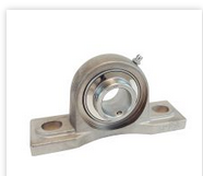
Fixed with through spacers under your rectangular profile.
Kind regards.
Using this solution, how could I fix the axle in the bearing and in the crank?
I thought about putting one, the problem is that I have few attachment points and that the environment in which it is going to be used may cause problems.
Almost agree with @Maclane
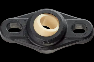
Personally I use this type of product from igus (used in particular for the bearings of the big eights
( Igus Bearing Insert - Google Search )
Four or two holes in the profile of the screws with nut and presto.
It is as strong as a ball bearing, especially to serve as an axle for a simple crank.
For the attachment for the crank it is a key (the cranks are supplied as standard with a slotting for key. (the shaft must also have the housing for the Misumi key, e.g. provides shafts with key-milling as standard)
A washer and a circlip are sufficient to prevent the axle from moving in the axial side opposite the crank.
Small remark for @naehu.beaubois, knowing the tangential force you would have to know the load to be moved (when it is a chain you can think of a carriage or a cable winding). Can you clarify this point because it will be useful for the pruning of the tree and the key. Note that the key will be used for both the pinion and the crank.
To pluche
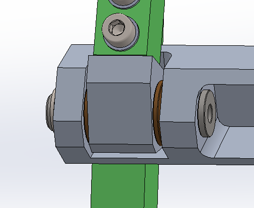
Views of the same montage with a circlips
In reality, the chain is used to roll up a bag. The two 25/50 sprockets rotate an axle or a bag is attached to pull it, in itself there is no big resistance, the bag itself must weigh 2 kg and the material inside must weigh 5 kg.
And the distance between the two axles is 460mm.
And at the same time I would like to know if for the circlips you should undersize the inner diameter. For example, I have an axle that is 12 mm in diameter, should I take a circlip of 11.7 mm in diameter?
Hello
For the clips if you don't make a groove on your axis, I offer you this type of clips.
Hello
For your crank, the bearing you chose simple is a 1-row ball bearing
so it will bear that radial force.
Since my company manufactures bearings, I would rather advise you
To use a bearing with 2 ball track angular contact, which will allow you
to have as much a radial as an axial resistance.
After if you tell us the size of the crank axle and the bore where will be located
the bearing, I will already be able to switch to a type of bearing suitable for this function  and also know about the load that your bearing will eventually have to support
I remain available 
I slightly modified my system following the previous advice. But here's what it looks like now.
The crank shaft is 24 mm in diameter and the internal bore of the bearing is 25 mm in diameter and for the load I think it is only the mass of the chain and that of the crank, which must correspond to 50 N.
I added a widening to the crank so that it can be the same diameter as the bearing. It's up to you to tell me if it's suitable or not.
I'm not going to lie, bearings are not what I know best ^^'.
humph! The landing is sized to lift an elephant, isn't it?
In addition I see a grease nipple which leads me to think that there is no bearing but a bronze or similar bearing.
Although we only see a very small part of the system, who says chain says protective housing even and especially if the second hand of the operator takes care of the bag. The CHST or other well-intentioned person will not fail to make a remark to you. 
Kind regards
Ahahah, I went to Norelem to do my research on the bearing, I took the one that had a larger diameter than that of my crank axle (also at Norelem).
But here are the technical details and the dimensions of it.
For me, a bearing of this type alone is not mechanical, the bearing is oscillating like a ball joint to be self-aligning.
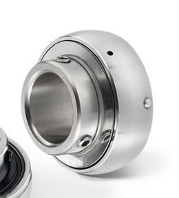
So nothing prevents the axis from rotating slightly here supplier doc as an example:
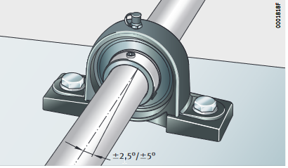
For me either 2 bearings or 2 bearings, bronze bearing but never a single bearing especially with a crank as a lever arm.
If I send you the 3D, would it be possible to show me the possibilities that can be optimal?
For me, put either a bearing on each side of the tube, or a bronze plastic ring or bearing, but in a quantity of 2 to have a longer guide and which prevents the axle from balluring.
Just like a bicycle crankset, the assembly includes 2 bearings.
The problem is that I don't have enough space to put 2 levels as shown in the diagram below.
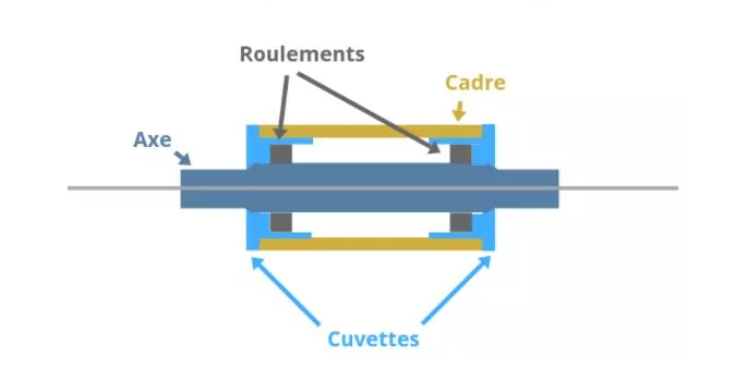
I have to be able to implement a single bearing where a roller to hold the axis, that's why I had a roller (maybe oversized it's true). I don't know if it's possible or useful to put only one roller/bearing.
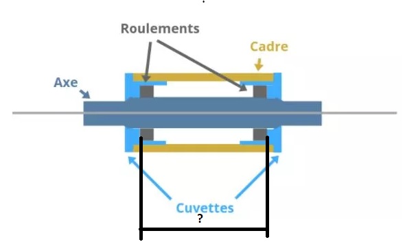
What size do you have or I drew the black lines?
It will allow me to advise you a bearing for your new configuration
Diameter of the axle remains the same as what you told me?
Because in this configuration depending on the size of the 2 meter single row bearings