I am attaching ac-cobra, for what purpose? It happens rather in reverse, and above all it will complicate the publication of the plans, otherwise is the top-down modeling not enough!?
Yes, reducing weight is part of the goal.
I also want to have an independent "complete assembled object" file, complete but not dependent on external references. This facilitates, shares, stores, and at least ensures that the object can be exploited no matter what.
1 Like
In my ideal world, I would program a macro that would just create a blank PRT file from an open assembly, extract the trees of each part in the assembly and copy them into the PRT (renaming items if necessary) but modifying the local origin of each part by the origin of the assembly, to ensure that their placement conforms to the assembly.
1 Like
It's a separate part that you save outside the assembly that you can move and then the links will be broken...
So first of all, thank you for the trick that I didn't know about and that will inevitably be useful to me one day. 
Unfortunately it does not respond to the request, but I understand the confusion because the word "merge" that I used is not the most appropriate. We had to understand "group".
I'm a bit lost, because I don't really understand whether to have a part with bodies or not because it can't be modified and the visual will be the same as a file saved in prt.
2 Likes
So first of all, my error in the recognition of functions is caused by the screws from the toolbox. If I exclude them from the loan, the recognition goes well. It's a shame but hey, let's just say it's already not bad.
Except that apparently you have to manually run a function recognition for each imported object, one after the other... We can't do a multiple recognition??
I probably expressed myself badly but to be clearer, let's say that I want what "register ASM as PRT" does, except that I don't want to have to go through useless reconversions of geometry conversions, nor a (des!!) recognition of functions. I want to keep functions, relationships, quotations, original names. A stupid cloning of the original tree of each room* in another common room, you know. (even more qd I see the time it takes to recognize the functions and that you have to restart it for each of the parts..., then rename them...). In the common room tree, the room trees should be hierarchized in individual folders of the room names.
We would be more on the "join" tool but without merging, just an addition of each tree*, as is, one after the other in the new target part. A concatenation without conversion, as a result. And always, ideally, in separate folders (in the featureManager eh).
It seems that only a macro will be able to meet these requirements 
*When I talk about "original tree", I mean "all the functions, plans, etc. that make up the room".
In fact what you want is to work on the multiple functions of your parts of the assembly in a part, I don't know if I expressed myself well 

In fact, I would like all the parts of an assembly to be "embedded" as they are in a single PRT.
The only difference visible in the tree is that the yellow "part" icon becomes a blue "folder" icon.
And indeed, it would allow you to edit all the "parts" (their functions grouped in folders) from the common room.
I don't think it's possible to do that 
The only way is to anticipate and build in a multi-body room and it won't help you in terms of lightening the part compared to an assembly because it's the functions that are heavy ...
Good luck because you're going to need 
 some
some
Hello
Basically, what you'd like to do is use the " insert part " function but instead of a part, it would be an assembly (impossible with this command) and be able to use the " propagate from the original part" option. I specify that you have to break the link with the original part to recover the construction tree.
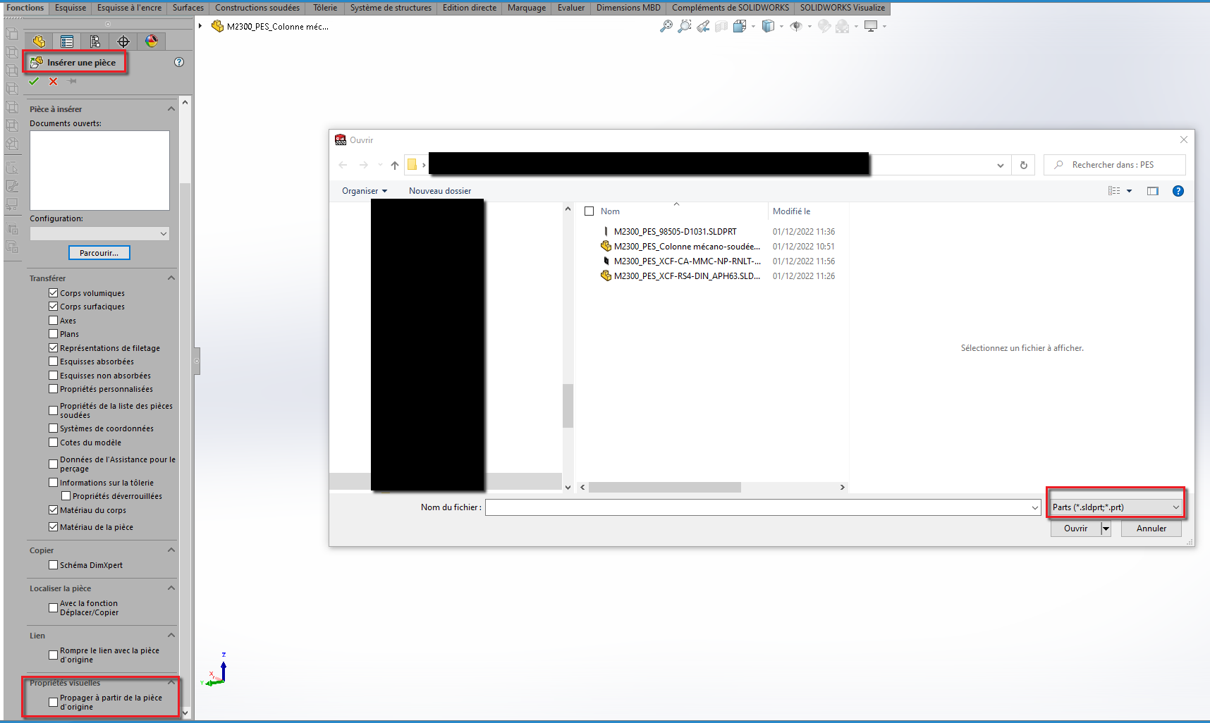
Except with a macro that would take each part of the assembly one by one and use this command, I don't see.
Good luck to you
1 Like
Hello @Sylk
The whole problem is in these two words: extract and copy. In other words: copy/paste...
Scanning the assembly component tree to identify the " source " parts is easily conceivable, but to my knowledge there is no copy/paste procedure of the build tree of each " source " part into the same " destination " part.
The only entities that can be " copied " from one part to another are sketches, curves, surfaces, and bodies, not geometric features.
In the absence of concatenation in a part, another avenue can be explored, which allows the backup to be reduced to a single file: virtualize all the components, i.e. integrate them into the assembly document.
The logic meets your expectations, even if the final document is an assembly and not a part.
The " Make Virtual " feature exists in the SolidWorks APIs. The links of the virtualized parts to the original parts are broken, but the build tree is preserved.
Kind regards.
1 Like
Hello @Rim-b
Excellent!! But not perfect... This is exactly the expected end result, except for the placement.
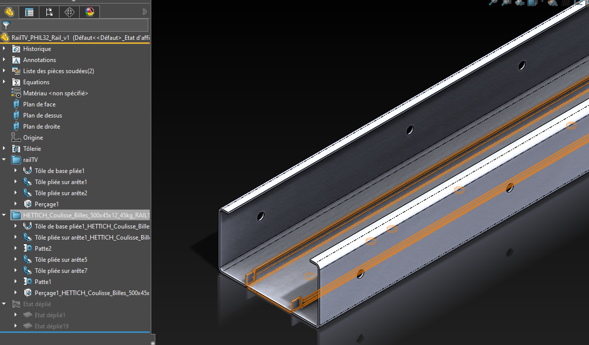
I insert a sheet metal part into the host sheet metal part, but I can't position it as desired. Is it possible to rotate the inserted sheet metal or are we limited to translation during insertion only?
The initial idea of going through an assembly was mainly to make the positioning simple, before it all ended up in a loan.
Hello
No, there are assembly functions (move with constraints).
But quite frankly, it's a gas factory, seen from my window, what you're trying to do.
You have to choose the right mode at startup (assembly or part within part) because "converting" afterwards is hours and hours of work. I'm not even sure that a macro can do it without generating positioning errors or at least will have to spend hours on this type of development.
2 Likes
I often use the insert part function and I confirm your dir cyril, the thing jumps at the slightest change in the tree sw doesn't like to play too much with the recovery bar,
For the copy of a function with macro I don't think either, I don't see how you can modify a hole or a removal of blind material or through everything without affecting the other bodies!
3 Likes
Hello
Inserting a part within a part works. On the other hand, if you have more than a dozen parts, it can very quickly be a hassle to manage. If you want it to work, the best thing to do is to probably not use constraints when inserting parts, but only positions.
A possible solution would perhaps be to make groupings of pieces that go together (so make sub-pieces) and then to insert a dozen pieces in a room.
NB: In terms of reconstruction, it may be difficult to manage in any case.
1 Like
Yes, I confirm and it's quite penalizing when a customer sends you an ASM in STEP format for example or other neutral format to make you do an RDM simulation. Not to mention that you lose all the constraints in the process.
Good luck ![]()
2 Likes
Hello.
Thank you all for your very informative answers!
So, I tested the insertion of a part in a part, the file weighs 2 times less than an assembly with the same part made virtual.
The fact that the weight goes from double to single is not negligible.
However, reading this topic, I have the impression that virtualizing the parts in an assembly remains by far the simplest, most practical and flexible solution.
What a shame that the file weighs twice as much...
The pee trick is indeed an interesting possibility, @froussel
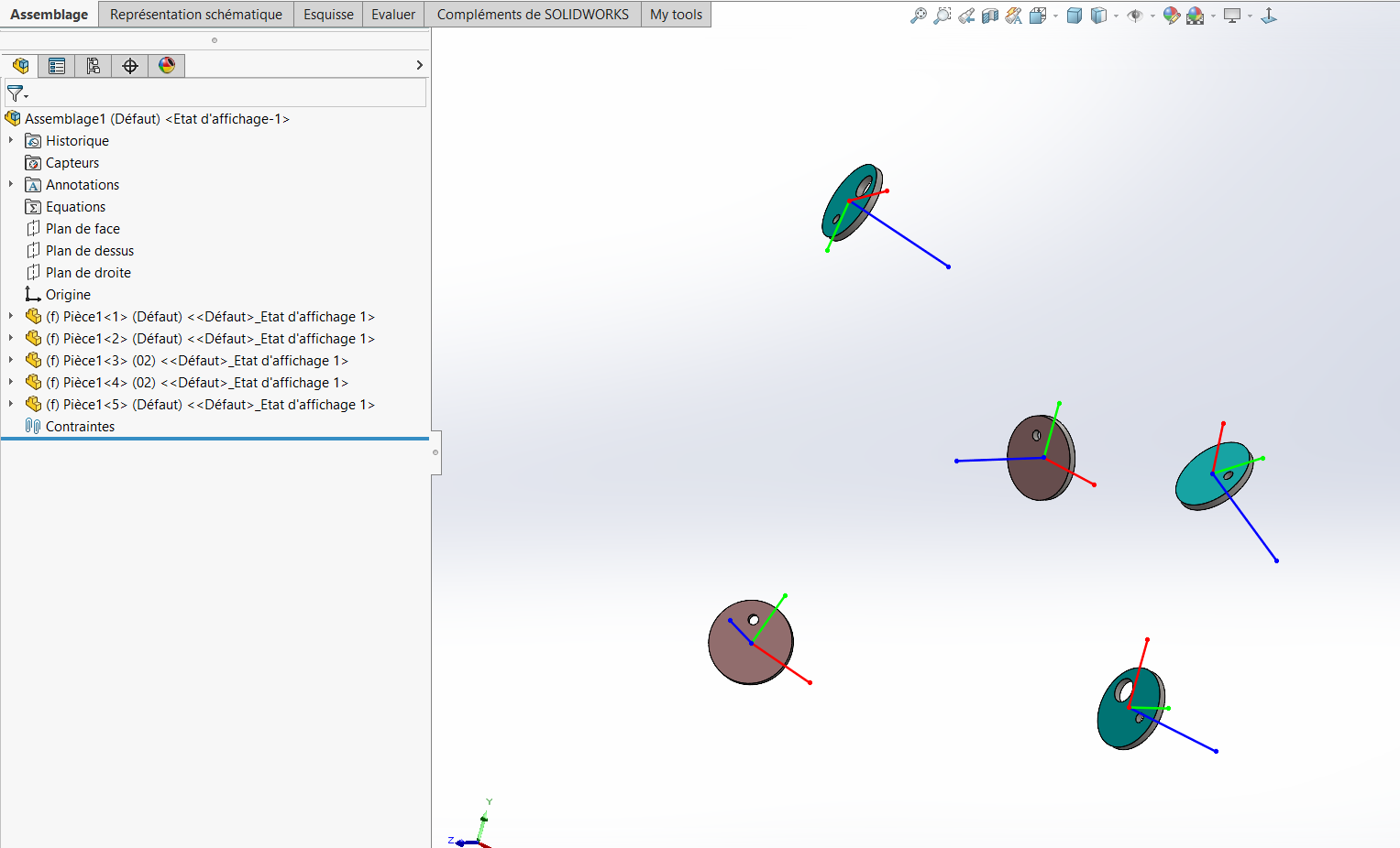
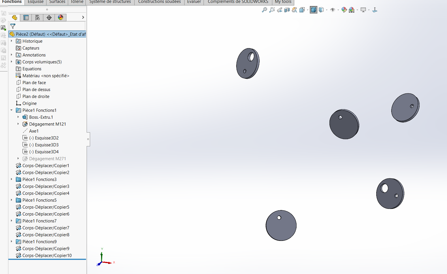
Checking in lapi, it seems to me that it's playable:
-
Browse the components one by one
-
Retrieve the position and orientation of the component relative to the assembly origin.
-
Insert the component into a part and break the link.
-
Detecting new bodies (a bit of a headache!) .
-
Apply orientation and displacement to these new bodies
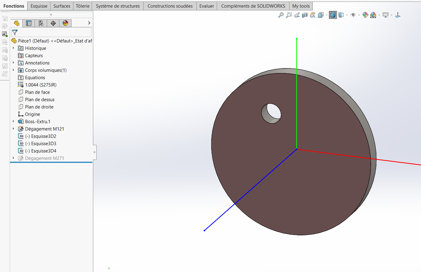
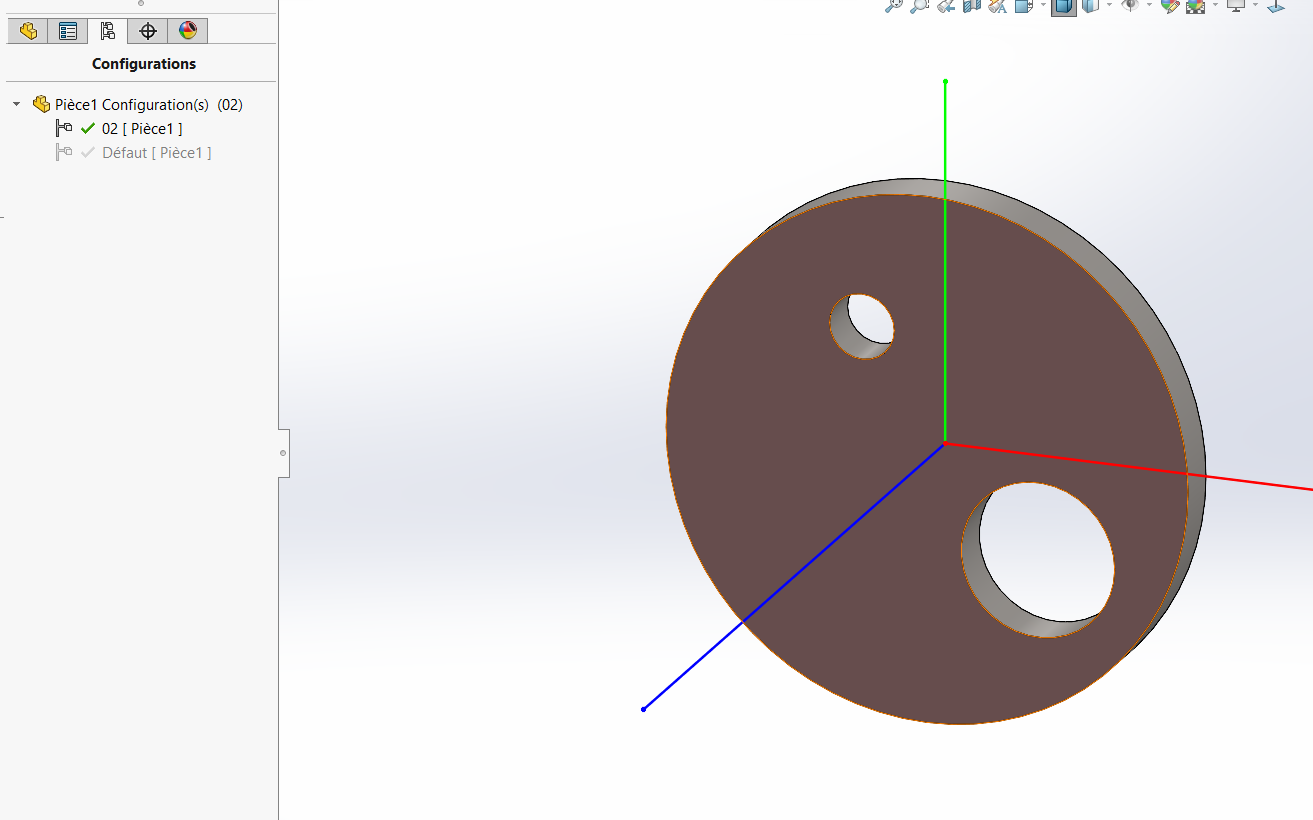
By breaking the link, the functions of the inserted part are recovered in the tree, the miracle is that SW only applies them to new bodies (it modifies the definition and action areas of all bodies to an automatic😀 selection) which avoids the problem I mentioned earlier, so the link is broken the tree and stable,
The only bimol I find is that these bodies are positioned in relation to the part origin not by stress interactions.
Not to say that the tree structure will be very very long depending on the number of components and their complexities
3 Likes
If attached a description of the points
(thanks to @Rim-b who mentioned the main function)
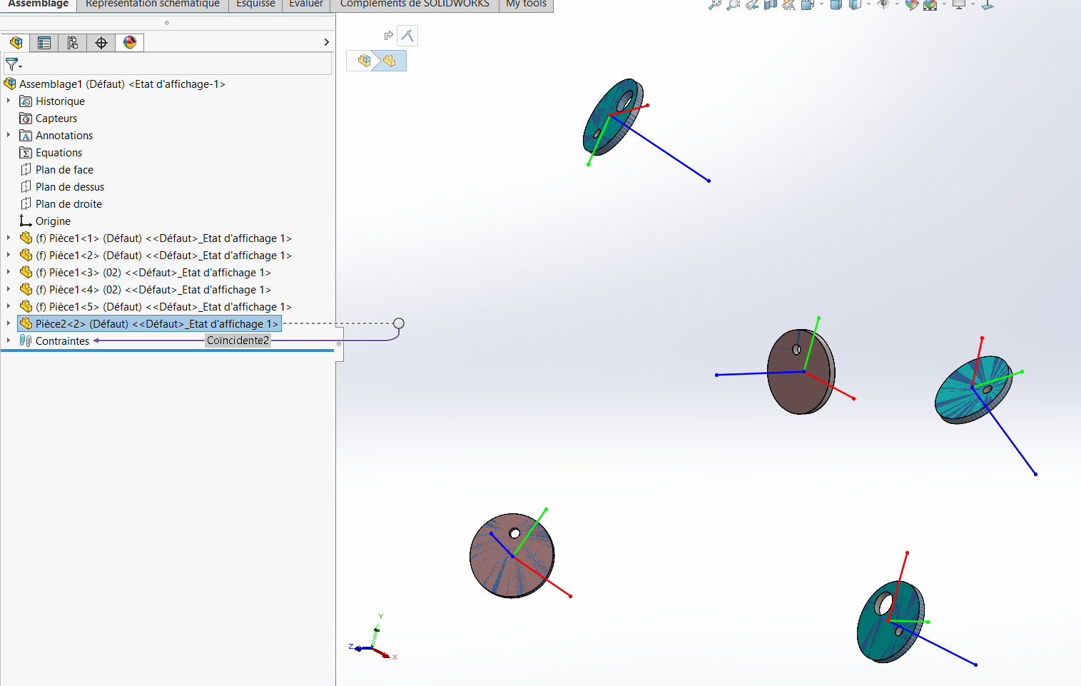
Assemblage1.zip (355.9 KB)
Option Explicit

Dim swApp As Object
Dim swmodel As ModelDoc2
Dim swpart As PartDoc
Dim swassembly As AssemblyDoc
Dim swMathUtils As SldWorks.MathUtility
Dim featmgr As FeatureManager
Dim pbodies As Variant
Dim selmgr As SelectionMgr
Const PI As Double = 3.14159265359


Sub main()

    Set swApp = Application.SldWorks
    Set swMathUtils = swApp.GetMathUtility
    Set swassembly = swApp.ActiveDoc
    Set swmodel = swApp.NewDocument("C:\ProgramData\SOLIDWORKS\SOLIDWORKS 2022\templates\Pièce.PRTDOT", 0, 0, 0)
    Set swpart = swmodel
    Set featmgr = swmodel.FeatureManager
    Set selmgr = swmodel.SelectionManager
    Dim comp As Component2
    Dim vcomp As Variant, vc As Variant
    vcomp = swassembly.GetComponents(False)

    For Each vc In vcomp
        Set comp = vc
        Dim pos As Variant
        pos = get_position(comp)

        pbodies = swpart.GetBodies2(0, False)
        swpart.InsertPart3 comp.GetPathName, 512, comp.ReferencedConfiguration()
        select_bodies get_bodies(swpart, pbodies)
        featmgr.InsertMoveCopyBody2 0, 0, 0, 0, 0, 0, 0, pos(5), pos(4), pos(3), False, 1

        select_bodies get_bodies(swpart, pbodies)
        featmgr.InsertMoveCopyBody2 pos(0), pos(1), pos(2), 0, 0, 0, 0, 0, 0, 0, False, 1
    Next
End Sub

Function get_position(comp As Component2) As Variant
    Dim pos(5) As Variant
    Dim swTransform As SldWorks.MathTransform
    Set swTransform = comp.Transform2

    Dim r11 As Double, r12 As Double, r13 As Double
    Dim r21 As Double, r22 As Double, r23 As Double
    Dim r31 As Double, r32 As Double, r33 As Double

    Dim r41 As Double, r42 As Double, r43 As Double
    Dim r44 As Double

    r41 = swTransform.ArrayData(9)
    r42 = swTransform.ArrayData(10)
    r43 = swTransform.ArrayData(11)
    r44 = swTransform.ArrayData(12)
    pos(0) = r41 * r44
    pos(1) = r42 * r44
    pos(2) = r43 * r44

    Set swTransform = swTransform.Inverse
    r11 = swTransform.ArrayData(0)
    r12 = swTransform.ArrayData(1)
    r13 = swTransform.ArrayData(2)

    r21 = swTransform.ArrayData(3)
    r22 = swTransform.ArrayData(4)
    r23 = swTransform.ArrayData(5)

    r31 = swTransform.ArrayData(6)
    r32 = swTransform.ArrayData(7)
    r33 = swTransform.ArrayData(8)

    If r13 < 1 Then
        If r13 > -1 Then
            pos(3) = atan2(-r23, r33)
            pos(4) = asin(r13)
            pos(5) = atan2(-r12, r11)
        Else
            pos(3) = -atan2(r21, r22)
            pos(4) = -PI / 2
            pos(5) = 0
        End If
    Else
        pos(3) = atan2(r21, r22)
        pos(4) = PI / 2
        pos(5) = 0
    End If

    get_position = pos

End Function

Function get_bodies(part As PartDoc, pbodies As Variant) As Variant
    Dim cbodies As Variant, bod As Variant, bod1 As Variant
    Dim vbodies() As Variant
    Dim row As Integer
    row = 0
    Dim isnew As Boolean
    Dim body As Body2
    Dim body1 As Body2
    cbodies = part.GetBodies2(0, False)
    If Not IsEmpty(pbodies) Then
        For Each bod In cbodies
            isnew = True
            Set body = bod
            For Each bod1 In pbodies
                Set body1 = bod1
                If body.Name = body1.Name Then
                    isnew = False
                End If
            Next
            If isnew = True Then
                ReDim Preserve vbodies(row)
                Set vbodies(row) = body
                row = row + 1
            End If
        Next
        Dim v As Variant
        get_bodies = vbodies
    Else
        get_bodies = cbodies
    End If
End Function

Sub select_bodies(bodies As Variant)
    Dim seldata As SelectData
    Dim bod As Variant
    Dim body As Body2
    Set seldata = selmgr.CreateSelectData
    seldata.Mark = 1
    swmodel.ClearSelection2 True
    If Not IsEmpty(bodies) Then
        For Each bod In bodies
            Set body = bod
            body.Select2 True, seldata
        Next
    End If
End Sub

Function atan2(Y As Double, X As Double) As Double
    If X > 0 Then
        atan2 = Atn(Y / X)
    ElseIf X < 0 Then
        atan2 = Sgn(Y) * (PI - Atn(Abs(Y / X)))
    ElseIf Y = 0 Then
        atan2 = 0
    Else
        atan2 = Sgn(Y) * PI / 2
    End If
End Function

Function asin(X As Double) As Double
    If Abs(X) = 1 Then
        asin = X * PI / 2
    Else
        asin = Atn(X / Sqrt(1 - X * X))
    End If
End Function
<< the code is devoid of error handling, test as needed, modify the path template, API 2022>>
2 Likes