And by changing the X,Y,Z coordinate system?
1 Like
Hello
A trick perhaps, if once generated the cube doesn't change anymore (?) would be to position a volume (or extrude a temporary extension on the body) that would delimit the top right corner on your last image (so at most aligned to the right with the right edge of the blue region, and stack aligned at the top with the top tip of the white region, so as to create a temporary framework that this addition will force.
It works with any corner by the way.
1 Like
A little prevention message by the way:
" Drink or build, you have to choose!" ![]()
![]()
4 Likes
Hello @a.eriaud
I have this macro that works well by orienting itself according to XYZ:
Dim swApp As SldWorks.SldWorks

Sub main()

    Set swApp = Application.SldWorks
    Dim swPart As SldWorks.PartDoc

    Set swPart = swApp.ActiveDoc

    If Not swPart Is Nothing Then

        Dim vBBox As Variant

        vBBox = GetPreciseBoundingBox(swPart)

        DrawBox swPart, CDbl(vBBox(0)), CDbl(vBBox(1)), CDbl(vBBox(2)), CDbl(vBBox(3)), CDbl(vBBox(4)), CDbl(vBBox(5))

        Debug.Print "Width: " & CDbl(vBBox(3)) - CDbl(vBBox(0))
        Debug.Print "Length: " & CDbl(vBBox(5)) - CDbl(vBBox(2))
        Debug.Print "Height: " & CDbl(vBBox(4)) - CDbl(vBBox(1))

    Else

        MsgBox "Please open part"

    End If

End Sub

Function GetPreciseBoundingBox(part As SldWorks.PartDoc) As Variant

    Dim dBox(5) As Double

    Dim vBodies As Variant
    vBodies = part.GetBodies2(swBodyType_e.swSolidBody, True)

    Dim minX As Double
    Dim minY As Double
    Dim minZ As Double
    Dim maxX As Double
    Dim maxY As Double
    Dim maxZ As Double

    If Not IsEmpty(vBodies) Then

        Dim i As Integer

        For i = 0 To UBound(vBodies)

            Dim swBody As SldWorks.Body2

            Set swBody = vBodies(i)

            Dim x As Double
            Dim y As Double
            Dim z As Double

            swBody.GetExtremePoint 1, 0, 0, x, y, z

            If i = 0 Or x > maxX Then
                maxX = x
            End If

            swBody.GetExtremePoint -1, 0, 0, x, y, z

            If i = 0 Or x < minX Then
                minX = x
            End If

            swBody.GetExtremePoint 0, 1, 0, x, y, z

            If i = 0 Or y > maxY Then
                maxY = y
            End If

            swBody.GetExtremePoint 0, -1, 0, x, y, z

            If i = 0 Or y < minY Then
                minY = y
            End If

            swBody.GetExtremePoint 0, 0, 1, x, y, z

            If i = 0 Or z > maxZ Then
                maxZ = z
            End If

            swBody.GetExtremePoint 0, 0, -1, x, y, z

            If i = 0 Or z < minZ Then
                minZ = z
            End If

        Next

    End If

    dBox(0) = minX: dBox(1) = minY: dBox(2) = minZ
    dBox(3) = maxX: dBox(4) = maxY: dBox(5) = maxZ

    GetPreciseBoundingBox = dBox

End Function

Sub DrawBox(model As SldWorks.ModelDoc2, minX As Double, minY As Double, minZ As Double, maxX As Double, maxY As Double, maxZ As Double)

    model.ClearSelection2 True

    model.SketchManager.Insert3DSketch True
    model.SketchManager.AddToDB = True

    model.SketchManager.CreateLine maxX, minY, minZ, maxX, minY, maxZ
    model.SketchManager.CreateLine maxX, minY, maxZ, minX, minY, maxZ
    model.SketchManager.CreateLine minX, minY, maxZ, minX, minY, minZ
    model.SketchManager.CreateLine minX, minY, minZ, maxX, minY, minZ

    model.SketchManager.CreateLine maxX, maxY, minZ, maxX, maxY, maxZ
    model.SketchManager.CreateLine maxX, maxY, maxZ, minX, maxY, maxZ
    model.SketchManager.CreateLine minX, maxY, maxZ, minX, maxY, minZ
    model.SketchManager.CreateLine minX, maxY, minZ, maxX, maxY, minZ

    model.SketchManager.CreateLine minX, minY, minZ, minX, maxY, minZ
    model.SketchManager.CreateLine minX, minY, maxZ, minX, maxY, maxZ

    model.SketchManager.CreateLine maxX, minY, minZ, maxX, maxY, minZ
    model.SketchManager.CreateLine maxX, minY, maxZ, maxX, maxY, maxZ

    model.SketchManager.AddToDB = False
    model.SketchManager.Insert3DSketch True

End Sub
My assemblies are always parallel to the top planes, so normal to Y, but not necessarily parallel to X (or Z).
I don't know if VBA macro functions would allow by selecting in advance the face that would be the orientation reference to generate a well-oriented 3D sketch...
If anyone has an idea of how to do this in macro, I'm interested ![]()
Hello
Indeed, there may be something to do with this macro...
But I don't know enough about it to get started...
I think you would have to dig into the " GetExtremePoint " function to find the extreme point while remaining parallel to a plane.
It's just an idea...
I think that on this forum there are macro pros, some have already helped me a lot...
Have a good weekend in advance.
2 Likes
Hello @MLG ,
If we retain the idea of an " envelope cube" (in fact a rectangular parallelepiped), the three generating planes are perpendicular. The first being chosen, it is then sufficient to give a direction in this plane for the trihedron to be completely constrained.
Starting from the Codestack macro proposed by @MLG and intended for a part, we think that we just have to adapt it to an assembly by sweeping the parts of the construction tree and forcing the projection directions.
Simple in appearance, but the few moments envisaged turn into hours. Fortunately, the weather was gloomy...
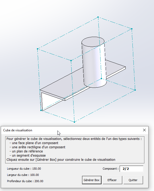
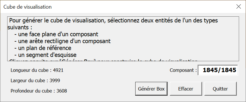
The result is available in the attached macro. Directions for use:
- An assembly must be opened in SolidWorks.
- A plane and direction (straight edge or sketch segment) are selected in this order in the graphics area.
- The macro is executed.
Results:
- The envelope cube is displayed as a 3D sketch in the assembly.
- the edges of the cube are specified in a UserForm.
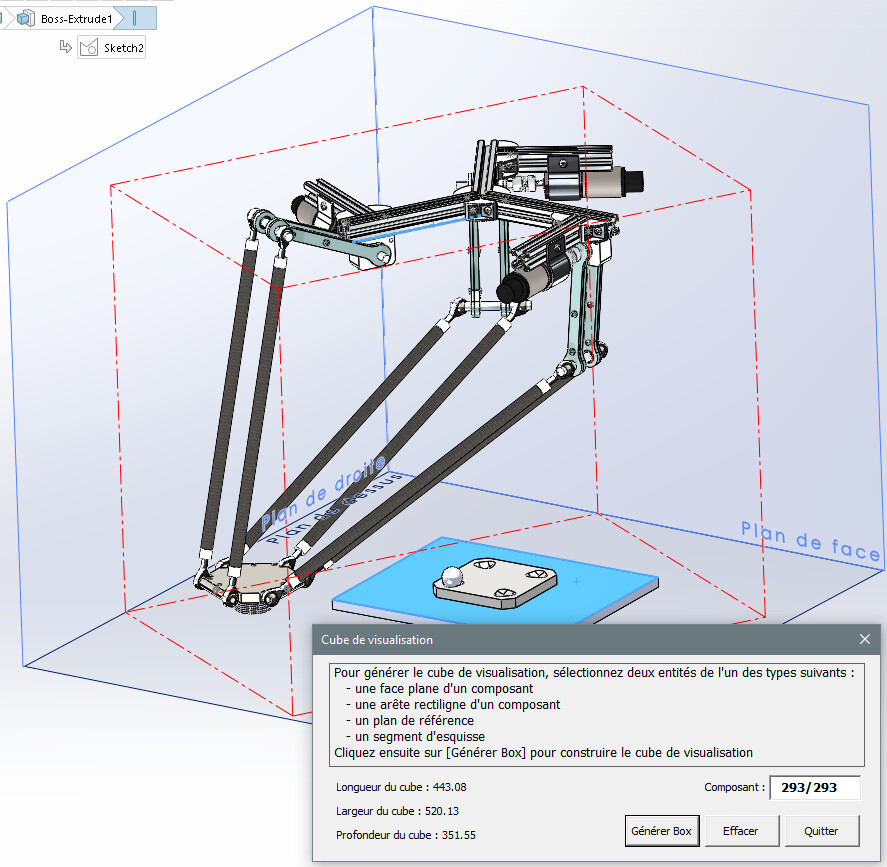
Weakness compared to the SolidWorks " visualization cube" is that the envelope cube is frozen on the geometry at the time of its creation. A further evolution of the forms of the assembly will not be taken into account.
As always, macro without safeguards, without guarantee of results, to be tested especially on large assemblies.
Kind regards.
Modified macro, to be downloaded below...
5 Likes
Hello @m.blt
I've gone through the code and there's work to be done!! WELL DONE ![]()
On the other hand, I tested on one of my assemblies, but nothing happens.
No error message, even if I force it by launching the macro on a coin.
Which, from what I could see in the code, should generate a warning window for me.
Any idea what to do?
1 Like
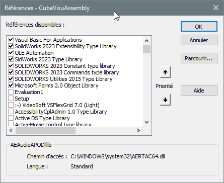
When launching the main sub from the editor via F8, it shows me a missing project or library error:
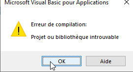
And looking at the error I understand better missing library (SW2023)
Maybe you have the same problem. Which version of SW do you have?
@m.blt I wanted to take a look out of curiosity and interest since in general your macros captivate me! ![]()
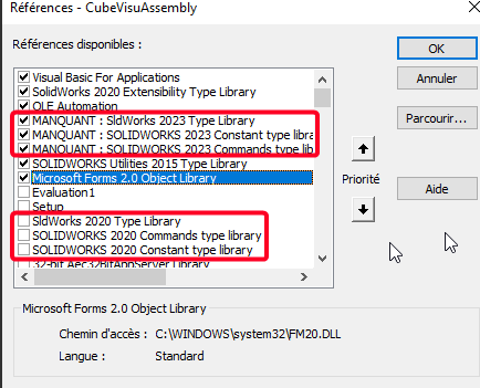
Edit: by unchecking what is missing and checking the 3 libraries version 2020 it works!
Once again I am amazed by this code:
3 Likes
The macro does not work on a part because it travels through the build tree of an assembly. Already there, you should have this message:
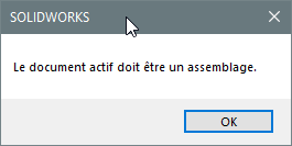
Personally, I tested the macro on several assemblies, the " heaviest " one having 278 parts, without noticing any anomaly. If you run the macro without selecting any objects, you should at least see the UserForm card.
I confirm @sbadenis's suspicion: the malfunction may be due to the absence of certain references to VBA objects. Here are the ones I use with the 2023 version of SolidWorks:
Also check that the sketch display is activated in the assembly, you never know...
Another clue: the macro was written with SW 2023. Maybe there's a non-existent feature if you're using an older version. Even though you should see an error message... Judging by the illustration of his message, @sbadenis made it work with a 2020 version
Does the assembly on which you tested the macro have a peculiarity that prevents it from working properly? You should share one of your assemblies and specify which version of SW you are using.
2 Likes
@m.blt
When I see this work, I tell myself that it was more than time for me to take the tangent that is parallel to the plane. Besides, a good deal is always appreciated.
C dlt
4 Likes
I applied the changes to the references by checking the 2022 for my version:
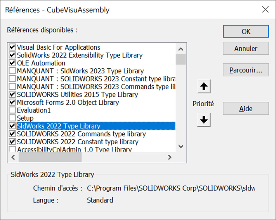
And the macro worked well, it's TOP @m.blt ![]() :
:
I just changed the ptLoc of the length and depth of the cube which for me, were inverted (ptLoc(4) and (1)), as well as the precision so as not to have a decimal:
        UserForm1.Label3.Caption = "Longueur du cube : " & Format(longueur(ptLoc(0), ptLoc(4)), "#####0")
        UserForm1.Label4.Caption = "Largeur du cube : " & Format(longueur(ptLoc(0), ptLoc(2)), "#####0")
        UserForm1.Label5.Caption = "Profondeur du cube : " & Format(longueur(ptLoc(0), ptLoc(1)), "#####0")
It's PERFECT.
On the other hand I would like to retrieve these values and associate them with variables in all the configs but I don't know where and how (sub, function ...) I have to insert this:
    Dim i As Integer
    Dim tConfig() As String
    Dim swErrors As Long
    Dim swWarnings As Long

    Do
    'récupère le document actif dans SW
    Set swModel = swApp.ActiveDoc
    If Not swModel Is Nothing Then

    'Boucle sur toutes les configurations
    tConfig = swModel.GetConfigurationNames
    For i = 0 To UBound(tConfig)

    'ajoute un propriété personnalisée "DIM-Lo"
    'Chr(34) permet d'ajouter le caractère "
    bRet = swModel.DeleteCustomInfo2(tConfig(i), "DIM-Lo")
    bRet = swModel.AddCustomInfo3(tConfig(i), "DIM-Lo", swCustomInfoText, Chr(34) & Format(longueur(ptLoc(0), ptLoc(4)), "#####0") & Chr(34))

    'ajoute un propriété personnalisée "DIM-La"
    'Chr(34) permet d'ajouter le caractère "
    bRet = swModel.DeleteCustomInfo2(tConfig(i), "DIM-La")
    bRet = swModel.AddCustomInfo3(tConfig(i), "DIM-La", swCustomInfoText, Chr(34) & Format(longueur(ptLoc(0), ptLoc(2)), "#####0") & Chr(34))

    'ajoute un propriété personnalisée "DIM-Ha"
    'Chr(34) permet d'ajouter le caractère "
    bRet = swModel.DeleteCustomInfo2(tConfig(i), "DIM-Ha")
    bRet = swModel.AddCustomInfo3(tConfig(i), "DIM-Ha", swCustomInfoText, Chr(34) & Format(longueur(ptLoc(0), ptLoc(1)), "#####0") & Chr(34))

    Next i
Do you have a lead for me?
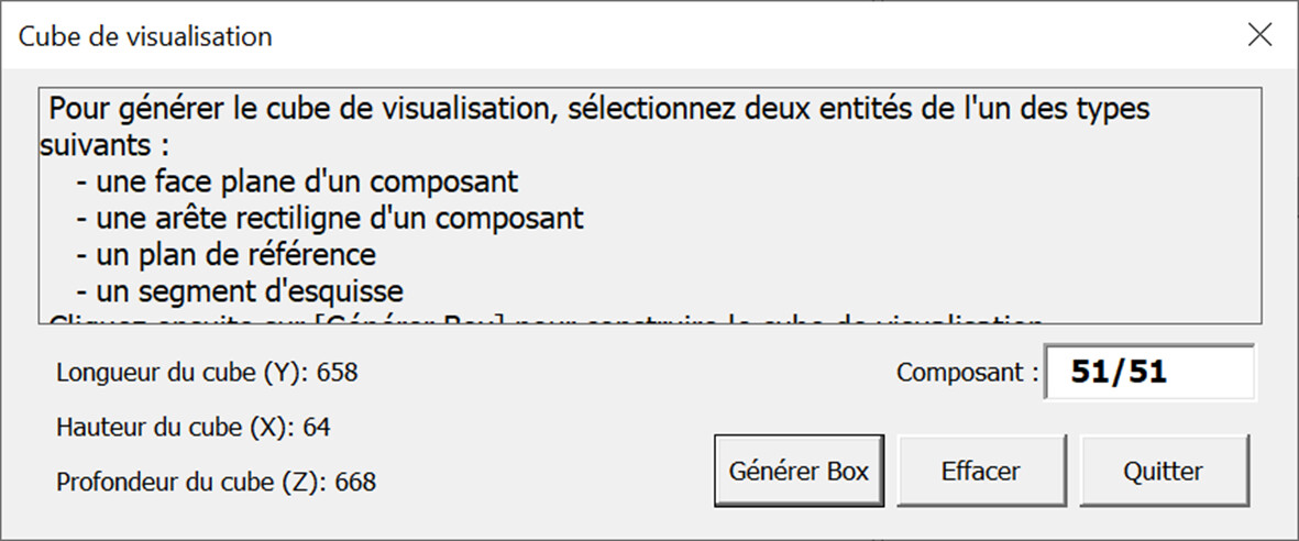
Hello @m.blt Bravo and thank you for your macro. Just a small suggestion; Specify the xyz axes of the dimensions indicated, in parentheses for example, because width length depth is relative to say the least.
1 Like
Hi all
One last (?) answer...
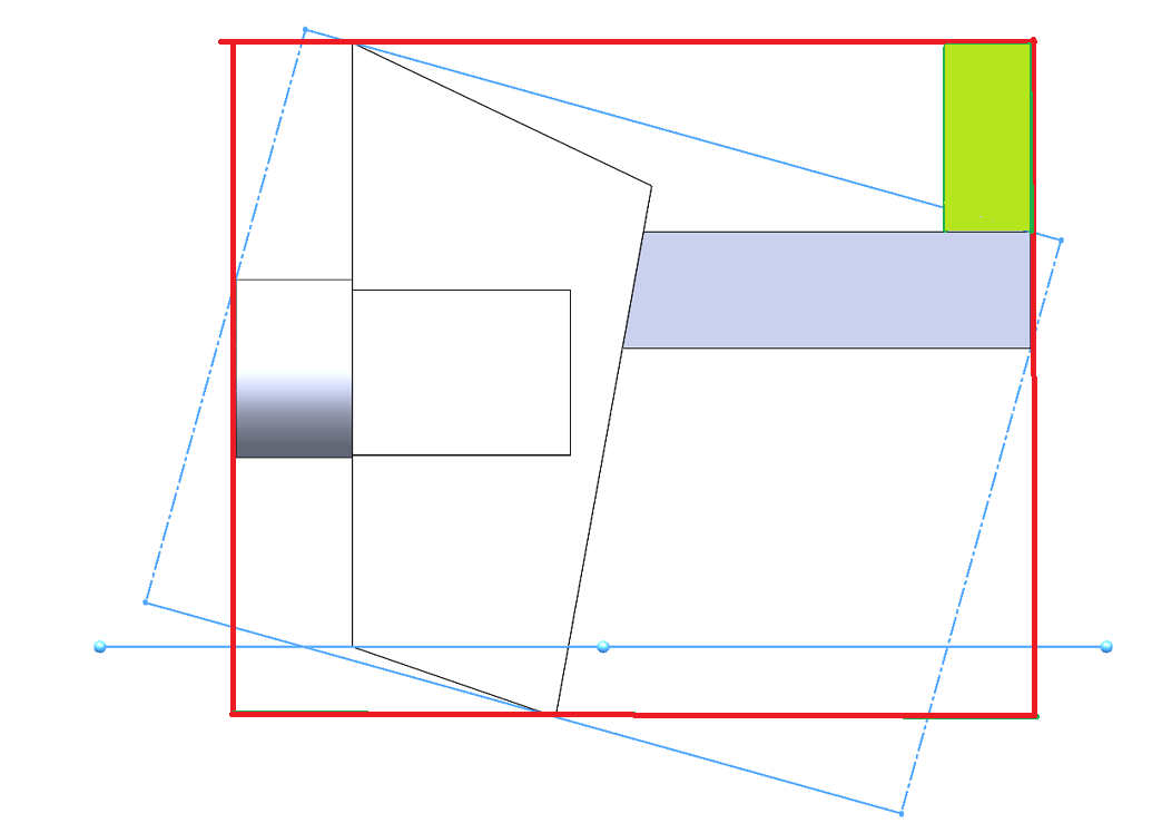
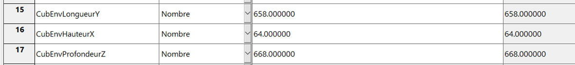
- The three dimensions of the envelope cube are written as properties in all the configs of the assembly;
- To fulfill @Sylk's
 wish, I added a local coordinate system at the origin of the cube, whose axes are aligned with the edges. In order to identify the X, Y and Z directions.
It seems to me that for @MLG, it is in order of height (X), length (Y) and depth (Z).
Order can be easily changed on lines 322 to 334.
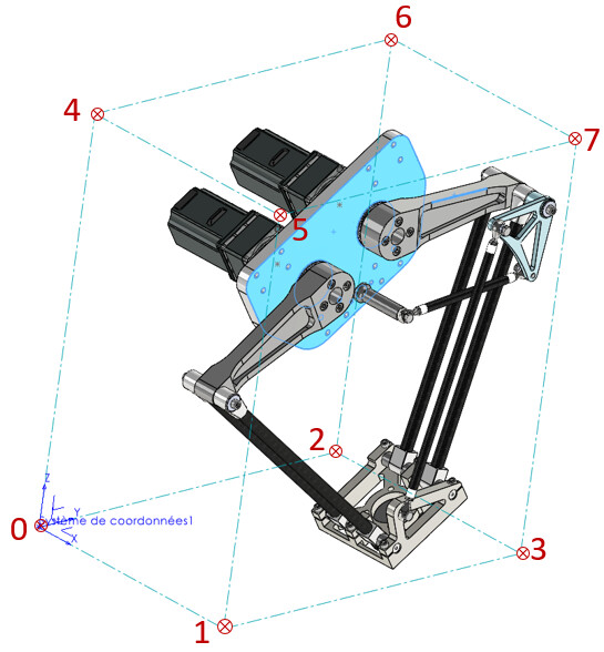
A small image to locate the vertices of the cube.
Kind regards.
CubeVisuAssembly.swp (223 KB)
2 Likes
Thanks again @m.blt
It works very well ![]()
I have a difference in the precision of the results between the dialog box and the variables in the properties (F8):
The precision is in units (no decimal places) in the dialog box
The accuracy is 6 decimal places
However, I applied the same FORMAT in the code between what is displayed in the dialog box and in the properties (F8):
        Dim valLONG         As Variant
        Dim valLARG         As Variant
        Dim valHAUT         As Variant


    Set ptLoc(0) = creationPt(min(0), min(1), min(2))
    Set ptLoc(1) = creationPt(max(0), min(1), min(2))
    Set ptLoc(2) = creationPt(min(0), max(1), min(2))
    Set ptLoc(3) = creationPt(max(0), max(1), min(2))
    Set ptLoc(4) = creationPt(min(0), min(1), max(2))
    Set ptLoc(5) = creationPt(max(0), min(1), max(2))
    Set ptLoc(6) = creationPt(min(0), max(1), max(2))
    Set ptLoc(7) = creationPt(max(0), max(1), max(2))

    For iPt = 0 To 7
        Set ptLoc(iPt) = ptLoc(iPt).MultiplyTransform(RgToCube)
    Next iPt

    TraceBox ptLoc

    lgAreteCube(0) = CalculLongueur(ptLoc(0), ptLoc(1))
    lgAreteCube(1) = CalculLongueur(ptLoc(0), ptLoc(2))
    lgAreteCube(2) = CalculLongueur(ptLoc(0), ptLoc(4))

    UserForm1.Label3.Caption = "DIM-Lo : " & Format((lgAreteCube(2) / 10), "#####0")
    UserForm1.Label4.Caption = "DIM-La : " & Format((lgAreteCube(0) / 10), "#####0")
    UserForm1.Label5.Caption = "DIM-Ha : " & Format((lgAreteCube(1) / 10), "#####0")
    UserForm1.CommandButton3.Enabled = True


    valLONG = (Format((lgAreteCube(2) / 10), "#####0"))
    valLARG = (Format((lgAreteCube(0) / 10), "#####0"))
    valHAUT = (Format((lgAreteCube(1) / 10), "#####0"))


    swConfNames = swModel.GetConfigurationNames             ' Liste des noms de configurations
    For iPt = LBound(swConfNames) To UBound(swConfNames)    ' Boucle sur les configs
        Set swCstPropMgr = swModel.Extension.CustomPropertyManager(swConfNames(iPt))

        swCstPropMgr.Add3 "DIM-Lo", swCustomInfoDouble, valLONG, swCustomPropertyReplaceValue
        swCstPropMgr.Add3 "DIM-La", swCustomInfoDouble, valLARG, swCustomPropertyReplaceValue
        swCstPropMgr.Add3 "DIM-Ha", swCustomInfoDouble, valHAUT, swCustomPropertyReplaceValue
    Next iPt

End Sub
And I tested by changing the decimals in my SW unit settings, but it doesn't change anything.
Do you have any idea where the problem comes from?
1 Like
Since you don't want decimals, the easiest way is to convert the variable lgAreteCube from type Double to Integer in the property generation statement.
Replacing the line:
swCstPropMgr.Add3 "CubEnvLongueurY", swCustomInfoNumber, CInt(lgAreteCube(1)), swCustomPropertyReplaceValue
by it:
swCstPropMgr.Add3 "CubEnvLongueurY", swCustomInfoNumber, CInt(lgAreteCube(1)), swCustomPropertyReplaceValue
To be adapted according to your ratings.
If you are looking for a more detailed format, you will have to use strings...
2 Likes
Thanks again @m.blt
It works very well.
I've been looking since yesterday on Codestack if there is a way to name the 3D sketch when it is made, or to retrieve the name of the last sketch created in the tree.
But I couldn't find anything about it.
I would need this to add the deletion of the 3D sketch at the end of the macro to clean up our assemblies once the variables are retrieved.
When I look at this code generated in Solidworks with a first 2D sketch delete and then a 3D sketch delete, there is no synthaxis difference except for the function name. Whether it's 2D or 3D, it's " SKETCH " that appears:
boolstatus = Part.Extension.SelectByID2("Esquisse3D1", "SKETCH", 0, 0, 0, False, 0, Nothing, 0)
Part.EditDelete
boolstatus = Part.Extension.SelectByID2("Esquisse1", "SKETCH", 0, 0, 0, False, 0, Nothing, 0)
Part.EditDelete
Do you know how to proceed?
Thanks in advance
1 Like
Hello
On the UserForm1 record, there is a [Clear] button that deletes the 3D sketch and the coordinate system associated with the cube. Provided that these are the last two functions of the tree, so that nothing is added after the cube is created.
As for retrieving the name of a sketch, the " Name " method is part of the " ISketch " class of the API (" swSketch.Name ", see line 377).
But if you have a variable pointing to the sketch, such as line 363 (" Set swSketch = swModel.SketchManager.ActiveSketch "), the " Select4() " method allows selection without having to search for its name, for example:
" ok = swSketch.Select4(False, Nothing) "
Probably inherited members, they are not documented in the help of the " ISketch " class, but are documented in other...
1 Like
Hello @m.blt
Thank you once again for your feedback.
I hadn't hit for the DELETE button actually.
I'll take a closer look at this to see when it acts in relation to the information of the variables I added... and to enrich my intellectual poverty in VBA ![]() .
.
By the way, in VBA I tinkered with it this morning...
A macro that retrieves the name of the last function in order to delete it.
As there is a 3D sketch and a trihedron, I double the command lines to remove the 2 functions.
I know, it's archaic ![]()
There is surely a way to make it simpler I guess ...
Option Explicit

Dim swApp As SldWorks.SldWorks
Dim swDoc As SldWorks.ModelDoc2
Dim swAssembly As SldWorks.AssemblyDoc
Dim swFeatureName As SldWorks.Feature


Sub SuppressionDeuxDernieresFonctions()

    Set swApp = Application.SldWorks

    Set swDoc = swApp.ActiveDoc

    ' Vérifie que le document SW est ouvert
    If swDoc Is Nothing Then

    MsgBox "Aucun document Solidworks ouvert"
    Exit Sub

    End If

    Set swAssembly = swDoc

'''Première passe pour supprimer le trièdre

    'Attribution nom dernière fonction
    Set swFeatureName = swDoc.Extension.GetLastFeatureAdded

    'Vérifie la selection de la fonction
    If swFeatureName Is Nothing Then

    MsgBox "Sélection fonction impossible"
    swDoc.ClearSelection2 True
    Exit Sub

    End If

    'Selection du nom
    swFeatureName.Select True

    'Suppression de la fonction
    swDoc.EditDelete

'''Deuxième passe pour supprimer l'esquisse 3D

    'Attribution nom dernière fonction
    Set swFeatureName = swDoc.Extension.GetLastFeatureAdded

    'Vérifie la selection de la fonction
    If swFeatureName Is Nothing Then

    MsgBox "Selection fonction Impossible"
    swDoc.ClearSelection2 True
    Exit Sub

    End If

    'Selection du nom
    swFeatureName.Select True

    'Suppression de la fonction
    swDoc.EditDelete

End Sub
1 Like
Hello @m.blt
I have a small question about the definition of the layout of the box.
I have a few cases where it doesn't totally fit at the maximum of what should be. In particular on round parts with fillets:
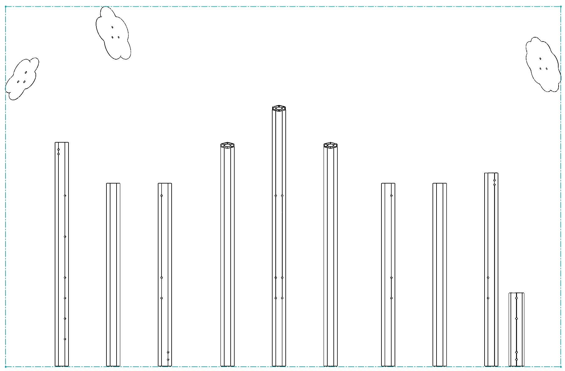
I have the case on the 2 pieces on the right and left:
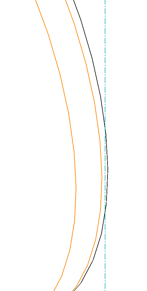
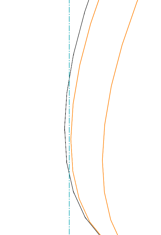
But I don't have the case on the top piece:
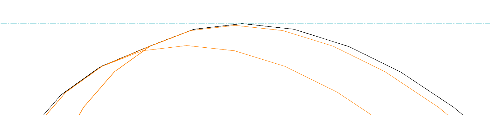
Where in the code can I intervene in order to obtain a good tangency?
In any case, the macro works great.
I brought my arrangements and extra functions and it's GREAT.
Thank you very much for the help provided.
Thank you in advance.
Hello
It is difficult to say what the origin of the problem you are raising. A few remarks:
-
What is the magnitude of the error, compared to the general dimensions of the assembly (in mm for example)?
-
Insofar as the observed defect requires a significant zoom, the display may be to blame...
-
The " GetExtremePoint() " method determines the outer limit for each part. This is a numerical calculation internal to the SolidWorks APIs. Is it rigorous? Like any numerical calculation, it uses a quality criterion to validate its search, a criterion unknown to the user.
On this point, SolidWorks Help comment about the " GetBodyBox " function which apparently uses the " GetExtremePoint " method:
IMPORTANT : The values returned are approximate and should not be used for comparison or calculation purposes. In addition, the bounding box may vary after the model is rebuilt.
The outlines of the " clouds" visible in the screenshots appear to be based on splines. Could this be the origin of the pb?
- The only calculations inside the macro are coordinate system changes that use the API's vector and raster functions. I don't see how they can generate the defect.
To conclude: I am not in a position to identify the origin of the problem. Can you share the example that is problematic? Even if it is degraded, or by private message...
Kind regards.
4 Likes