I may say something stupid but I take the risk; Couldn't the " structure " function help, especially for joins?
Hello
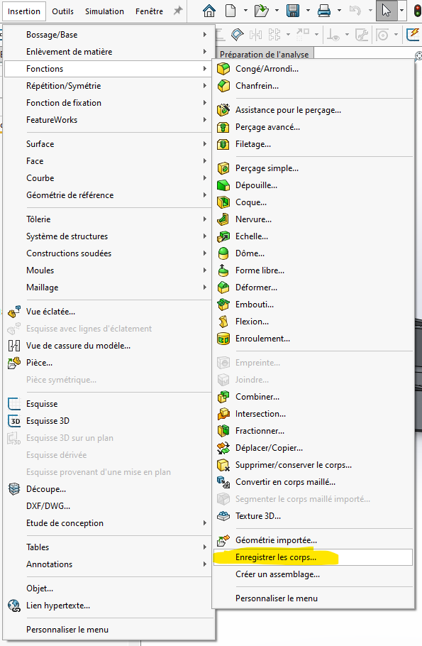
I am looking for the union/subtraction/intersection functions of solids in SW 2020,
Can you tell me please?
Regarde la fonction combiner @Alfoncpasmamob :
https://help.solidworks.com/2021/french/SolidWorks/sldworks/t_combining_bodies_add.htm
Of course!!!
Thank you
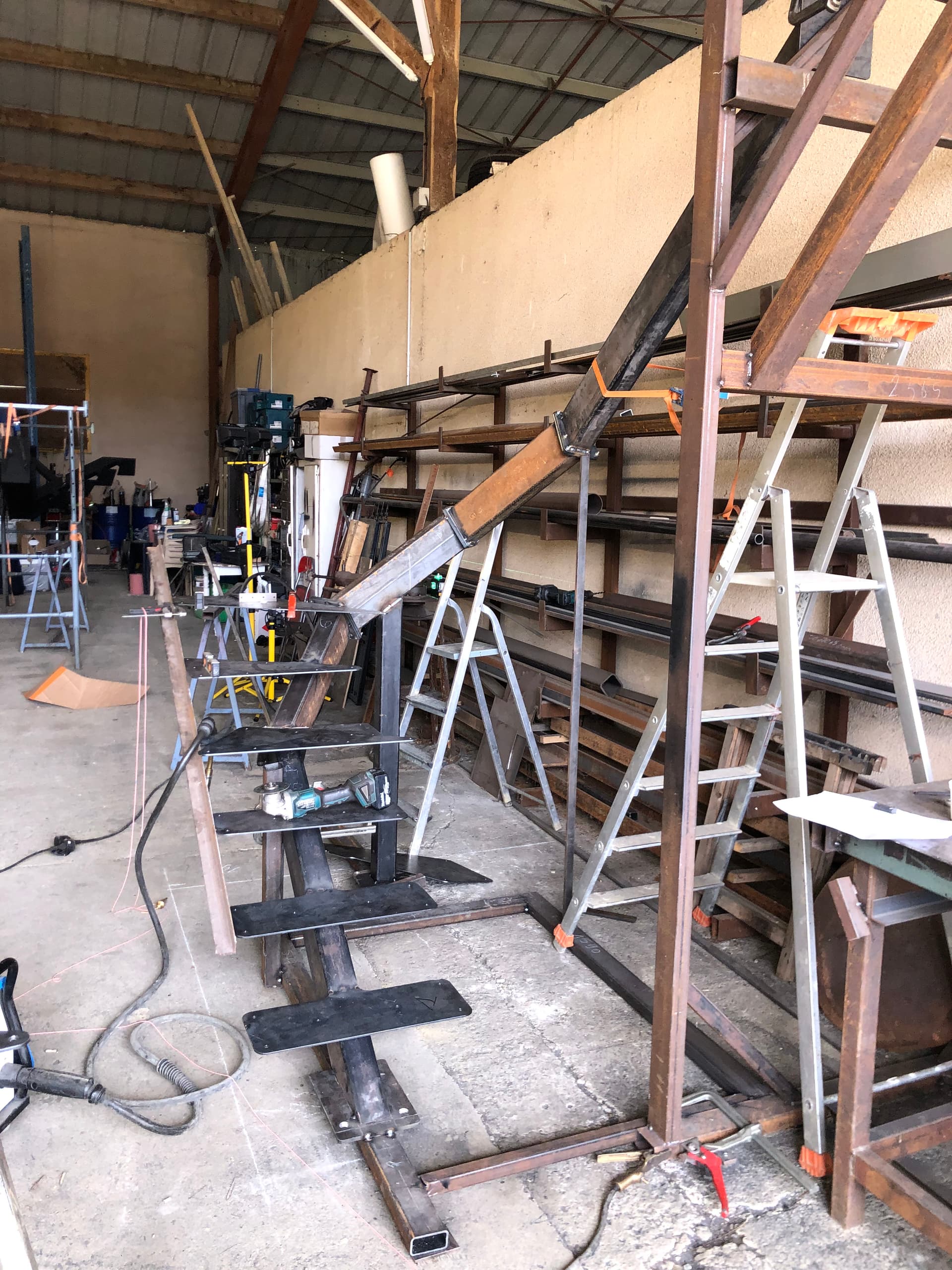
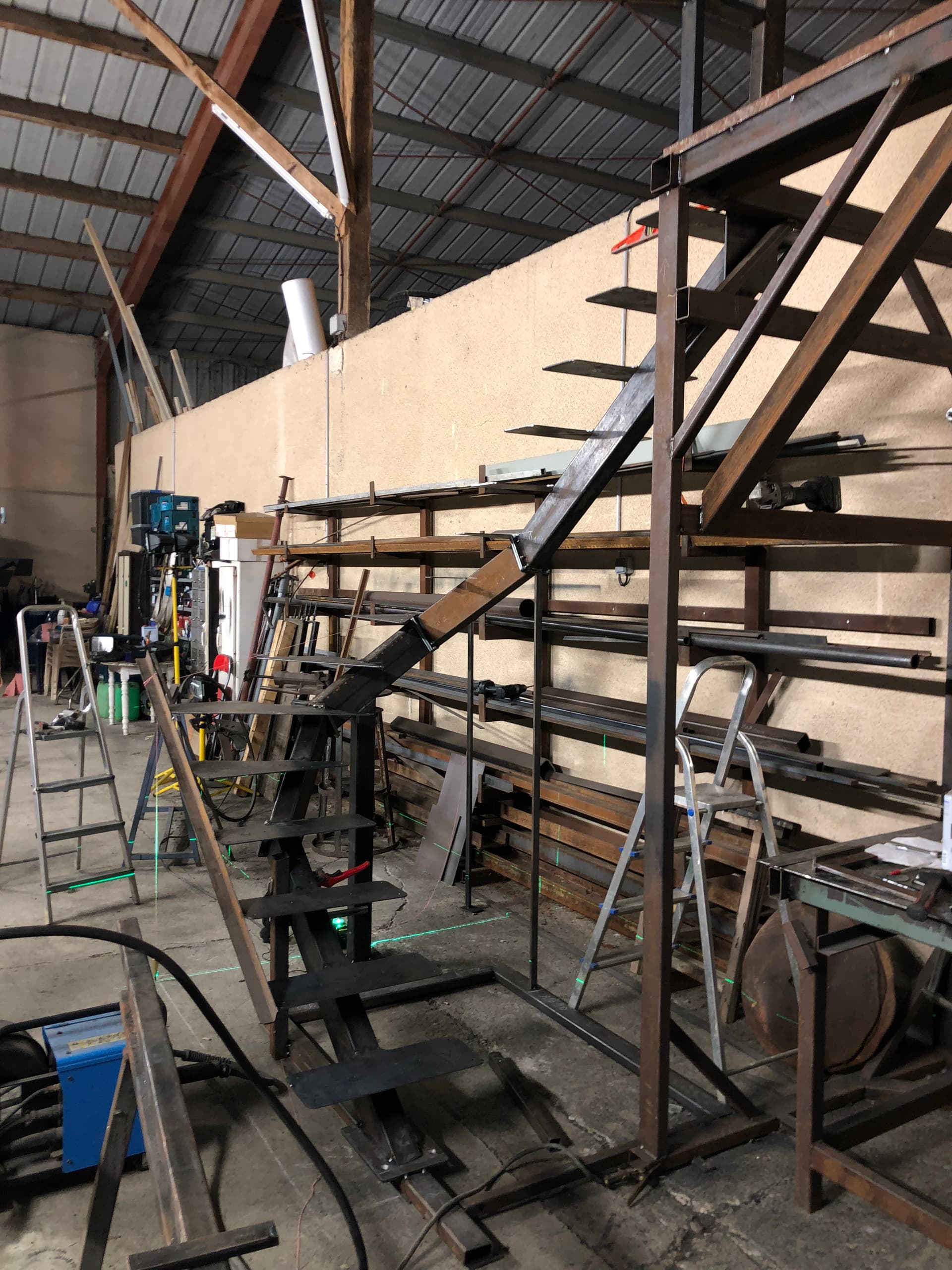
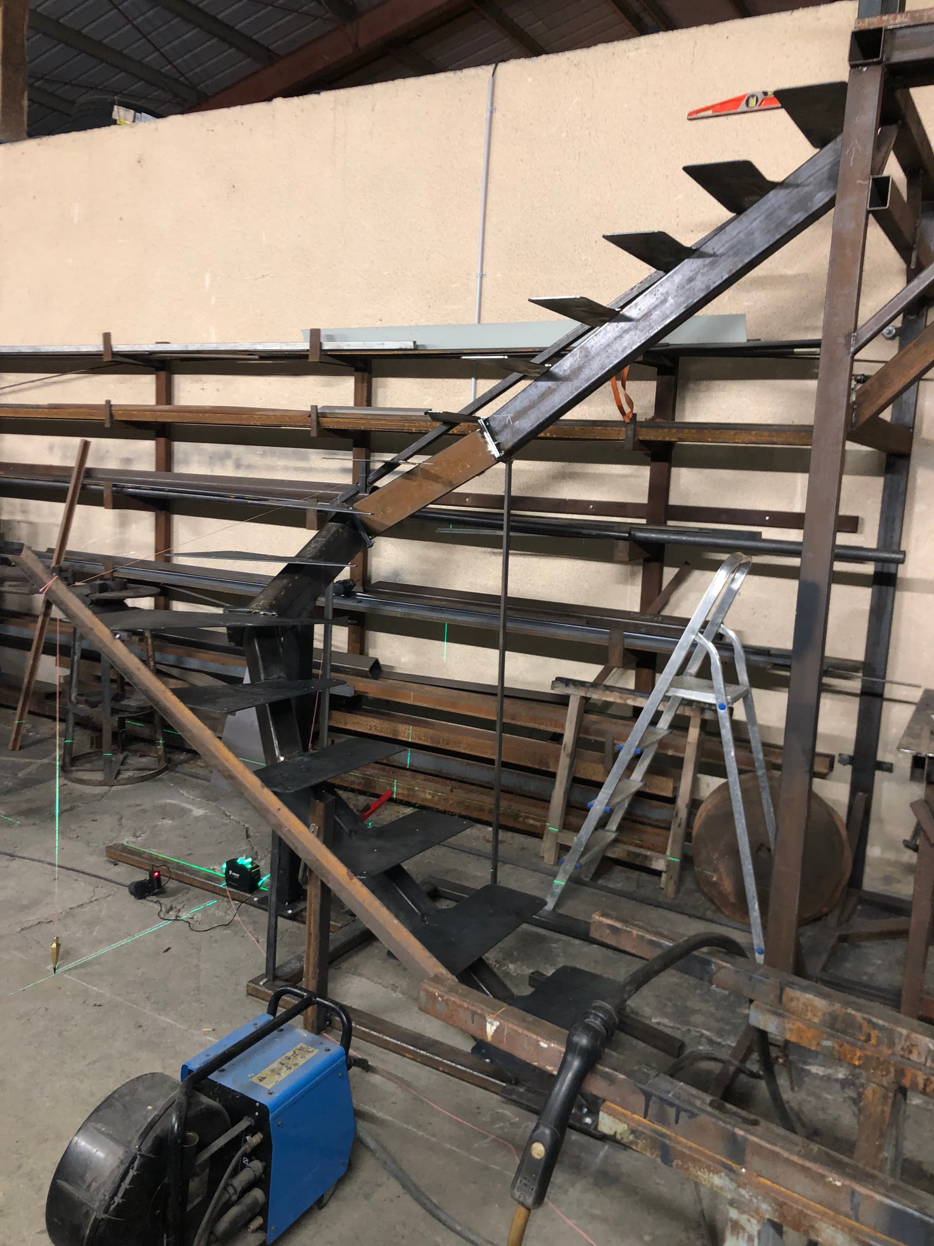
Attached to the staircase, don't look at the creation tree, too complicated because I think I did it wrong, of an imported 3D DXF ...
4b. SLDPRT (3.0 MB)
Also, how do you extract each tube for a drawing?
Thank you
As you're in real 3D, it's not going to be easy to put them in a drawing.
Watch the videos posted here:
https://forum.mycad.visiativ.com/t/squelette-piece-inserer-dans-une-piece-probleme-lesquisse-est-non-contrainte/112280/14
I'm thinking for you of this solution that seems to me the most suitable:
Otherwise, the ' body selection' function in the properties of the drawing view is for you.
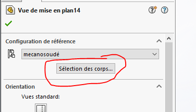
(incredibly efficient/practical compared to the management of display states which is totally buggy)
Hello;
For your drawings I propose the " Relative Views "...
https://help.solidworks.com/2022/french/SolidWorks/sldworks/t_insert_relative_view.htm?id=5fbca5a9c66449afbebad1f9dfab665e#Pg0
Nowadays I think that this is most often more than enough; The drawings are mainly informative documents for boilermakers/machinists equipped with machine tools (multi-axis laser cutting).
3 Likes
It seems indeed the simplest for all the views of the tubes that are drawn in real 3D.
Combined with body selection, MEP doesn't have to be that complicated to do
As the cuts will be made in part with a grinder, make sure that the drawings include all the indications for the tracing. Also add a flow rating
Thank you
plasma cutting for tread supports and plate sets, for tubes, band saw
Thank you for the feedback with the " real ", and don't forget to close the subject with the answer that brought you closest to your solution.
all the answers have served me,
Thank you all
Without a doubt, but to close a subject, you have to make a compromise and choose the one that best answered the initial question.

From what I see, it would be more like this:
https://forum.mycad.visiativ.com/t/limon-tube-80-140-escalier-2-4-tournant/112245/14
May be
Kind regards
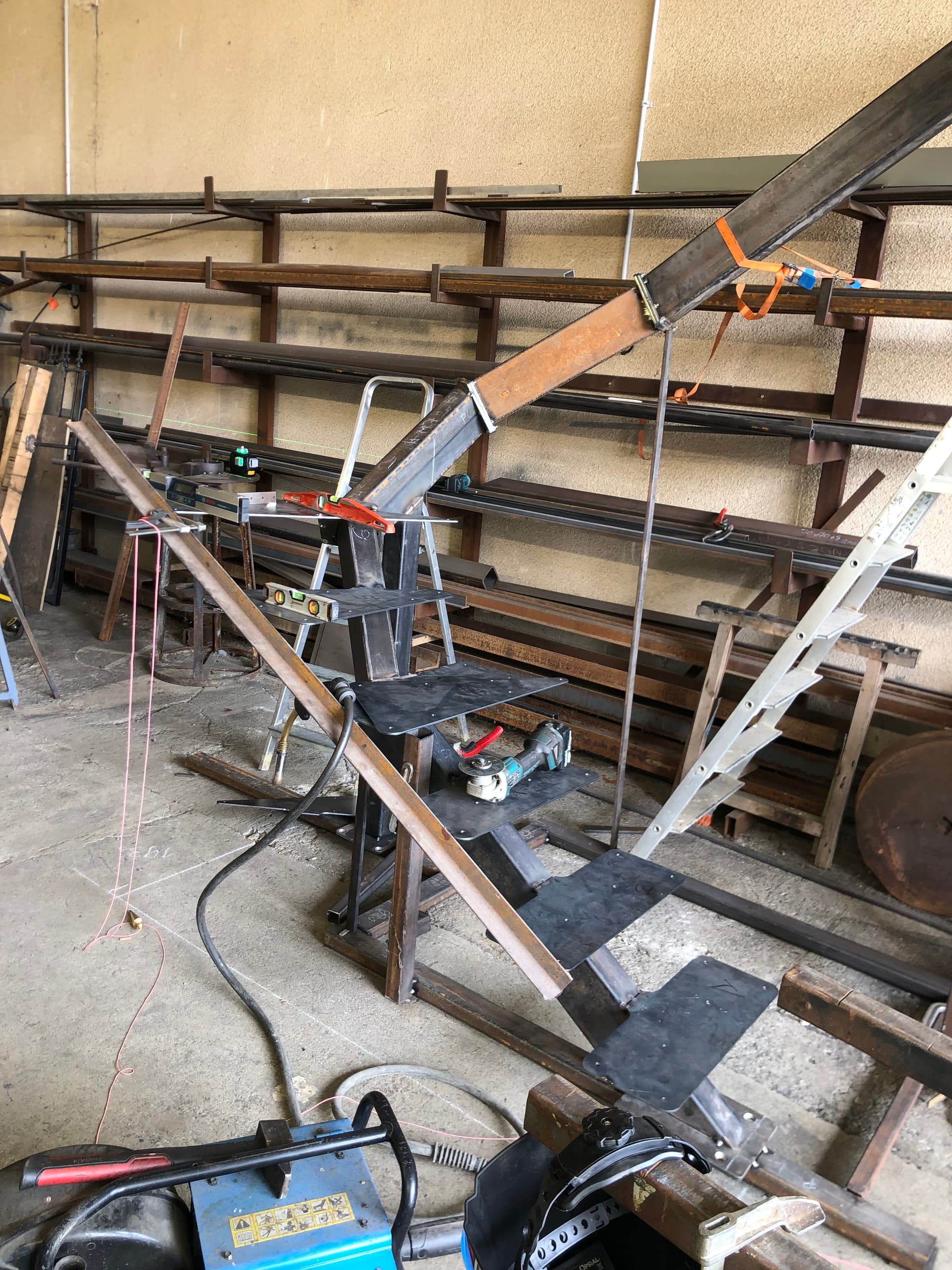
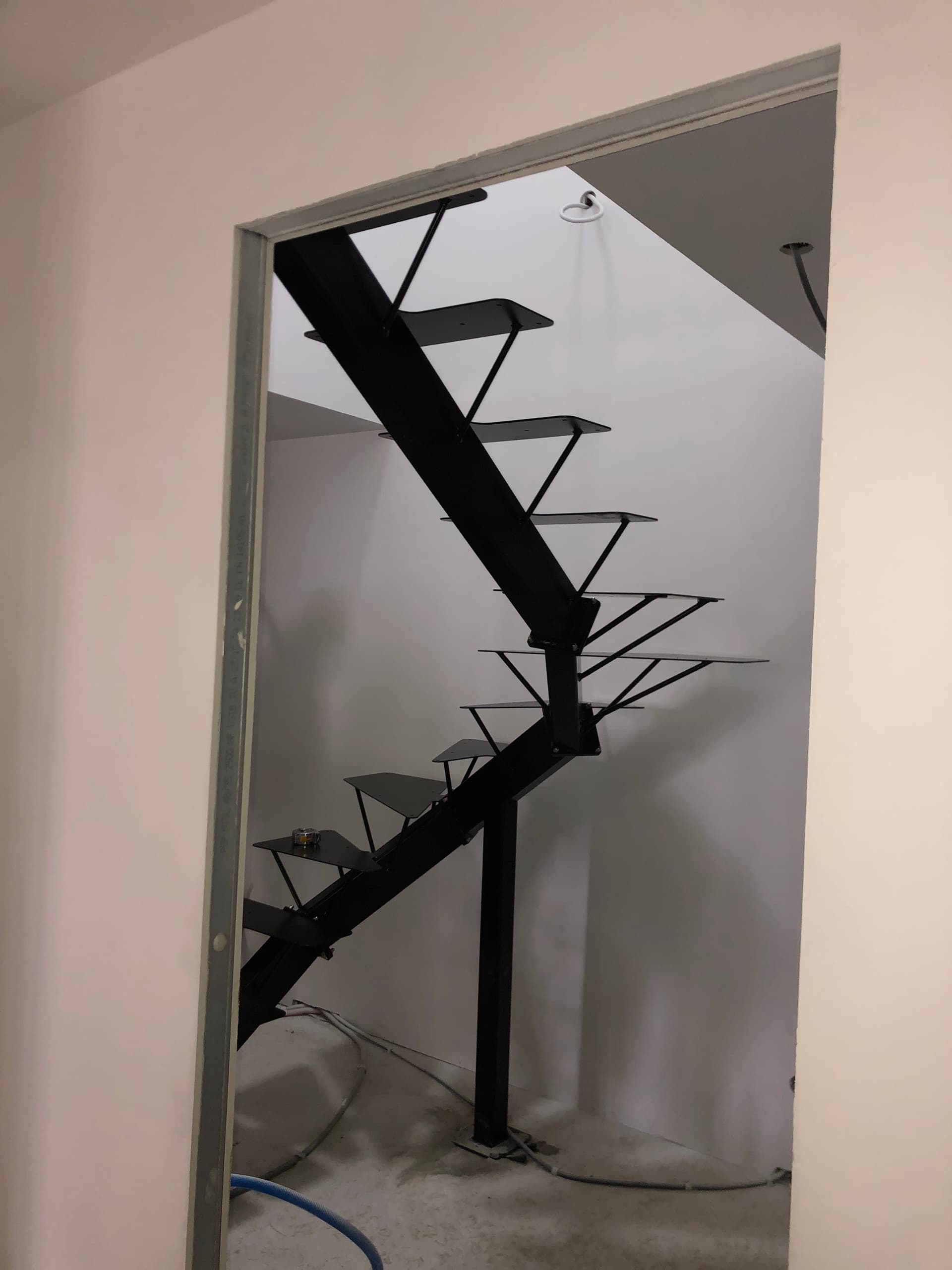
The metal part is gone for thermo-lacquering, and the wooden steps are being made,
I will publish images of this staircase finished/placed in its place
1 Like
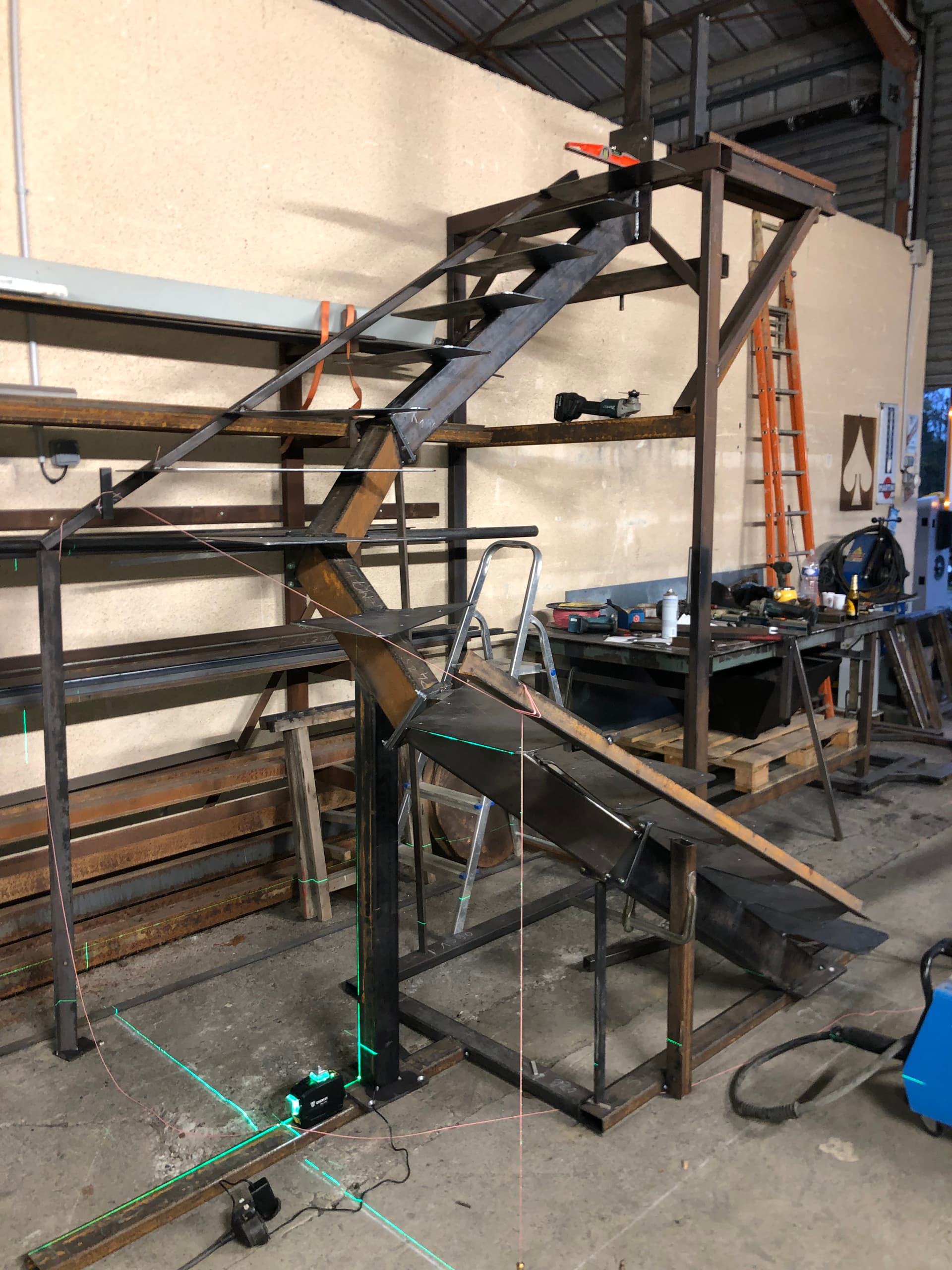
assembly metal part, while waiting for the wooden steps
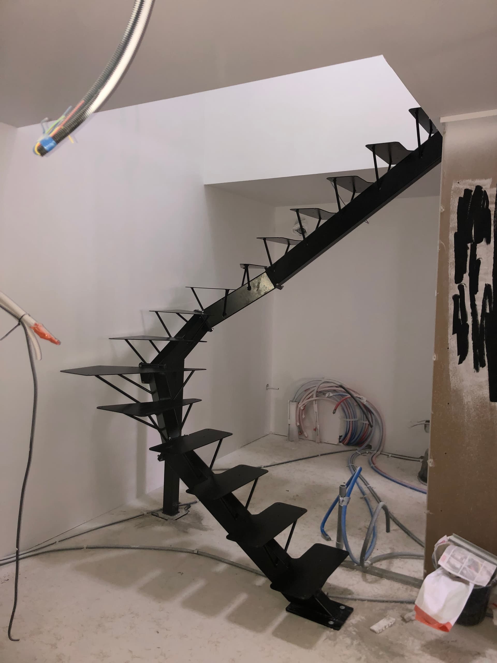
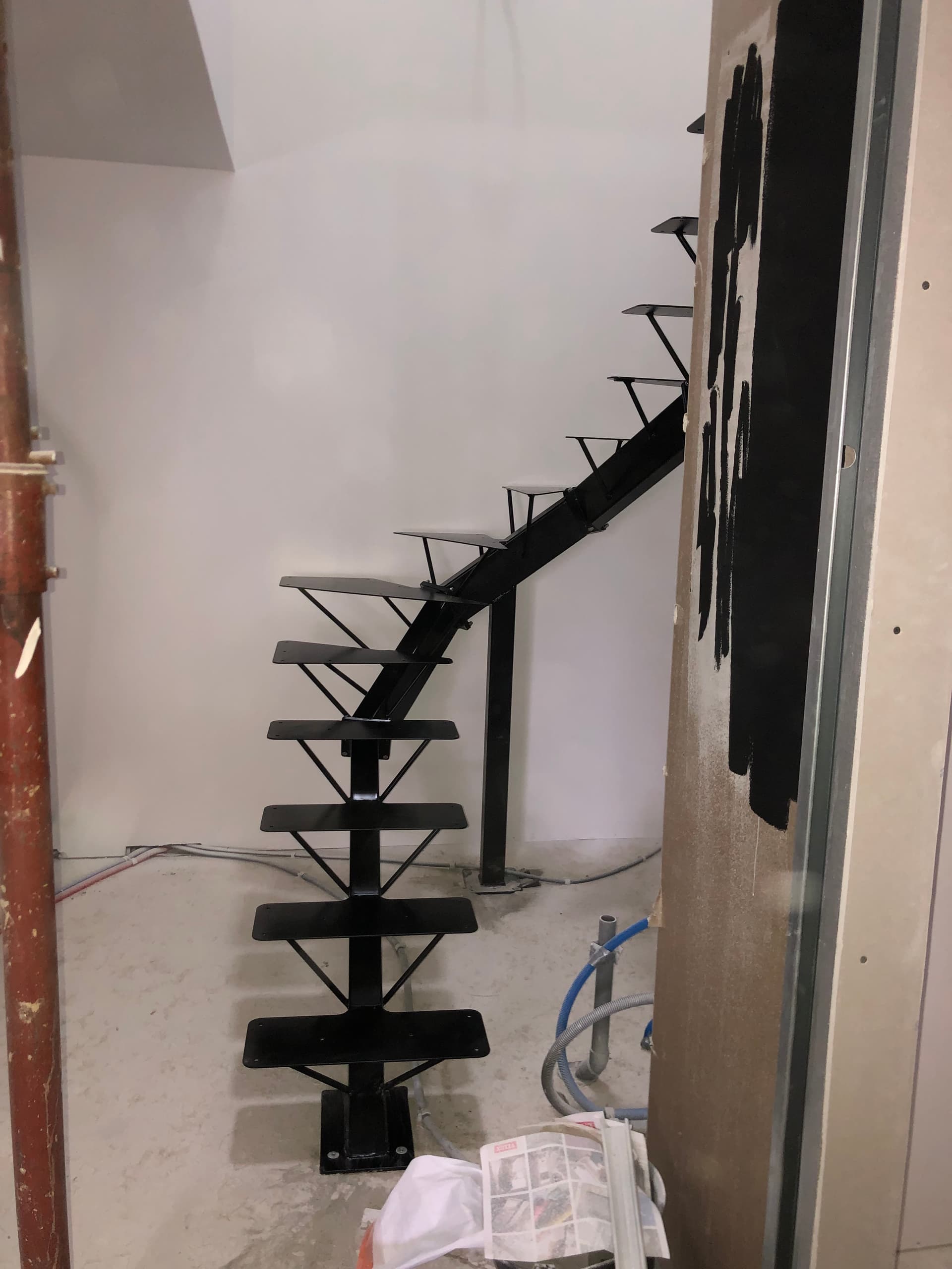
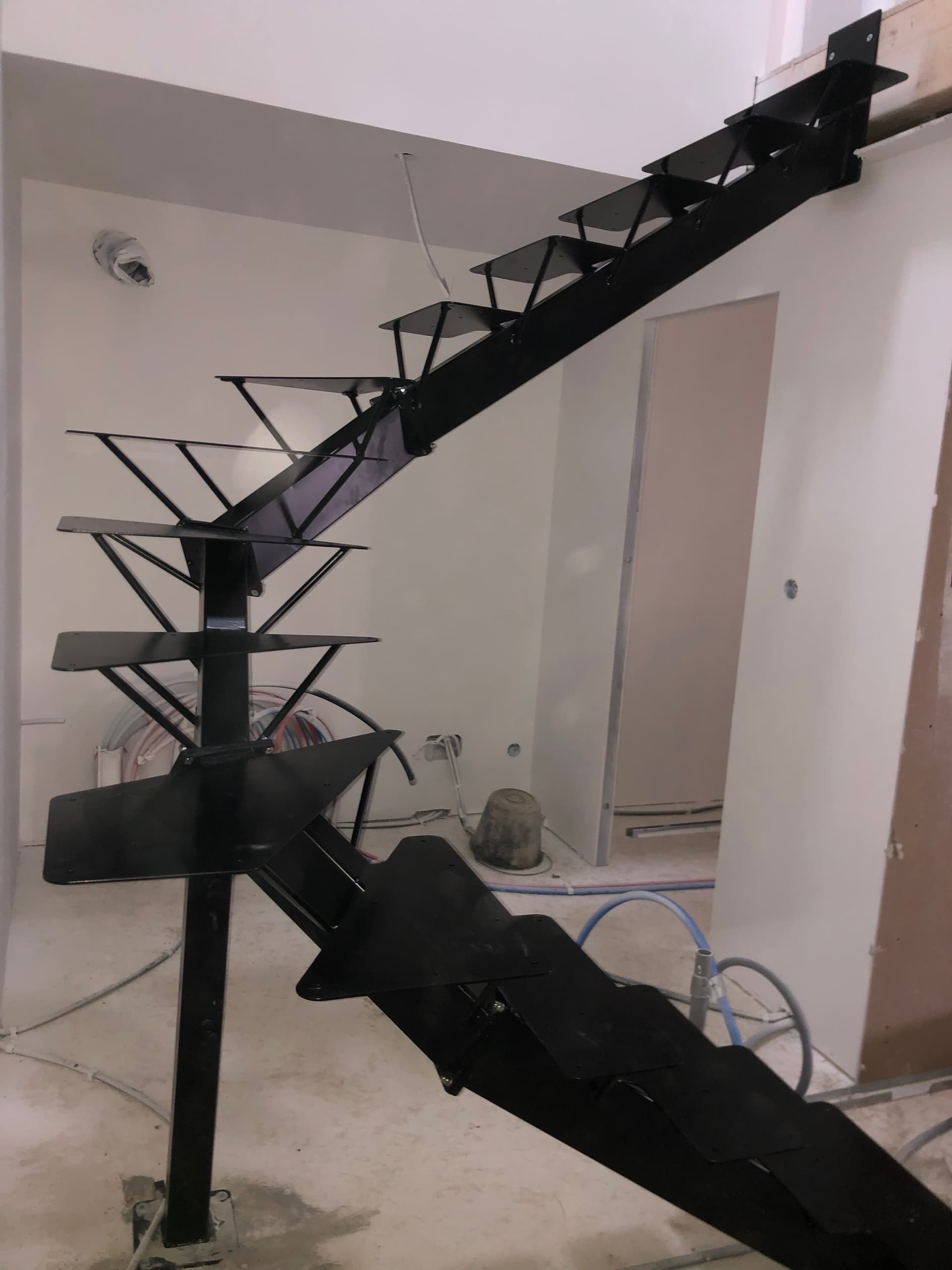
3 Likes