Bjr
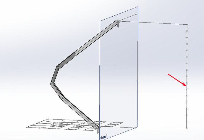
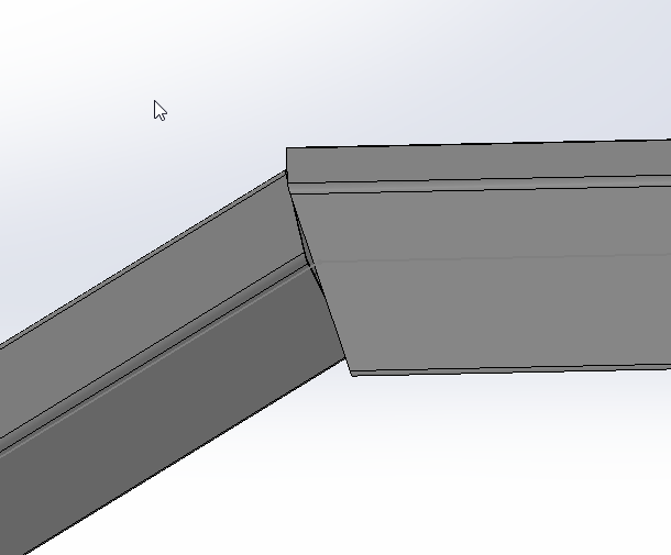
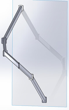
Attached is an SW 2020 file with a 3D sketch for the stringer, I can't keep the verticality of the tube for this stringer with the mechanically welded function, ???
Is there a solution please?
2b mechanic. SLDPRT (159.8 KB)
Hello
I think you would have to make several groups in your function to be able to rotate each tube independently of the others and thus keep the surfaces tangent to each other.
The most complicated thing will be to determine the angle...
Good luck.
I agree with @a_eriaud , on the other hand it will be " cotton " for the landing of the profiles:

If you want to keep your model, you need to determine precisely the angle to be applied in the output
For this reason, a cylindrical profile is usually used for this type of staircase.
Thank you, it's a removable stringer assembled with plates at the end of each tube, so as long as it keeps the verticality ...
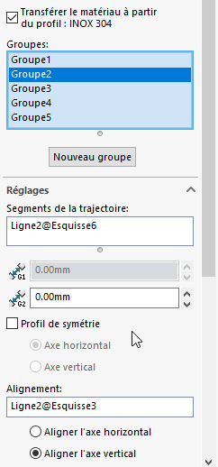
To orient the tube:
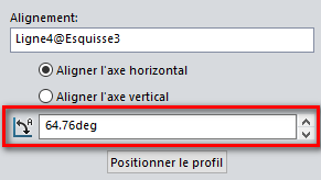
Make one group per segment, then for each group in alignment fall the segment indicated in my capture:
And check align the vertical axis:
And the tubes are well oriented. (vertical axis tube // to reference sketch)
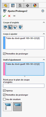
On the other hand, for the adjustments between tubes (rectangular), it's a different story:
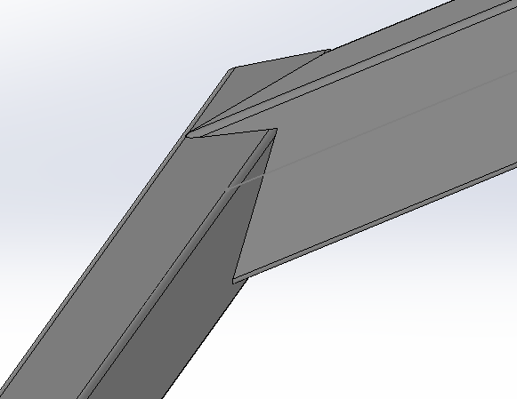
Instead of making a function per tube you make a group per tube:
To do this, click on a new group, in the Mechanically welded element function:
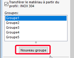
I can't attach my part since the 2023 version.
But coming from a sw2020 version I know it worked the same way.
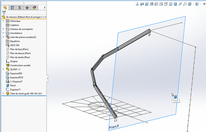
By extending the lines-groups I obtain the crossing of the tubes to cut them
cf attached file
thank you again
2b mechanic +. SLDPRT (190.2 KB)
If you put a plate between the 2 you can then adjust your tubes:
And from the easiest to place your turntable and readjust if necessary.
yes, thank you
Hello
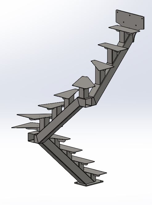
Since you want to assemble the different stringer sections with turntables, I advise you to keep your sketch as a basis for drawing each section individually. Then assemble them.
Easy to edit. If you change your sketch, all the sections will change.
That is how I would proceed.
In this type of case I systematically go through a small dish between each change of orientation, much easier to assemble.
Hello
I agree with @Le_Bidule for a section-by-section definition, which allows the construction of the geometric entities necessary for construction.
As I did not have SW 2020, I wrote a document explaining the approach I used...
See attached pdf file.
Limon2bMecano.pdf (726.3 KB)
I may say something stupid but I take the risk; Couldn't the " structure " function help, especially for joins?
Hello
I am looking for the union/subtraction/intersection functions of solids in SW 2020,
Can you tell me please?
Regarde la fonction combiner @Alfoncpasmamob :
https://help.solidworks.com/2021/french/SolidWorks/sldworks/t_combining_bodies_add.htm
Of course!!!
Thank you
Attached to the staircase, don't look at the creation tree, too complicated because I think I did it wrong, of an imported 3D DXF ...
4b. SLDPRT (3.0 MB)
Also, how do you extract each tube for a drawing?
Thank you
As you're in real 3D, it's not going to be easy to put them in a drawing.
Watch the videos posted here:
https://forum.mycad.visiativ.com/t/squelette-piece-inserer-dans-une-piece-probleme-lesquisse-est-non-contrainte/112280/14
I'm thinking for you of this solution that seems to me the most suitable:
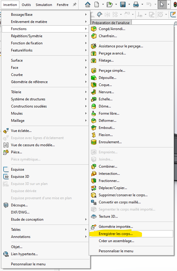
Otherwise, the ' body selection' function in the properties of the drawing view is for you.
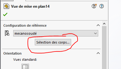
(incredibly efficient/practical compared to the management of display states which is totally buggy)
Hello;
For your drawings I propose the " Relative Views "...
https://help.solidworks.com/2022/french/SolidWorks/sldworks/t_insert_relative_view.htm?id=5fbca5a9c66449afbebad1f9dfab665e#Pg0
Nowadays I think that this is most often more than enough; The drawings are mainly informative documents for boilermakers/machinists equipped with machine tools (multi-axis laser cutting).
