Hello/Good evening
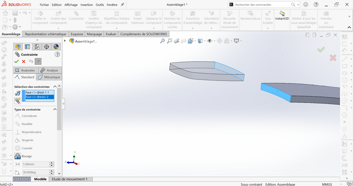
I am a student who participates in the current race project, my goal is to create a " shell " of a car on Solidworks. After inquiring on several forums to thicken my hull, I was advised to thicken each part in a different file and then to join them in an assembly. My problem is the following, I can't constrain my 2 parts in my assembly so that they are coaxial
Do you have any solutions?
Good evening
Constrains one edge in the transparent part and the other, and then on the opposite edge a corner of the part (one point) or two points on opposite corners
CDLT
Hello @mathis.hsf ,
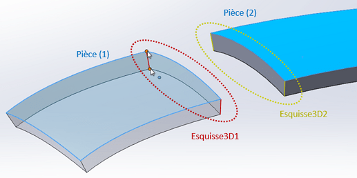
Based on your description, we can imagine that the two parts were generated by similarly thickening two surfaces belonging to them (in blue on the illustration). Because these surfaces have a double curvature, the end faces defined in the thickness are not geometrically simple in the general case.
And even if the mode of generation makes them particular from a theoretical point of view (plane, cylindrical, etc.), it is not certain that SolidWorks identifies these particularities. Very little chance in these conditions of power forces them to be coincident or coaxial. Moreover, do they have an axis?
In the same way, are the edges defined in the thickness, in red for part (1), in yellow for part (2), known as straight by SolidWorks?
Not sure, even if it is tempting to think so...
The track proposed by @Zozo_mp is an approach to the coincidence you are looking for:
- make a 3D sketch in the part (1) with the two segments joining the vertices defining the thickness of the part: Sketch3D1 ;
- do the same for part (2): Sketch3D2 ;
- Define a coincidence constraint of two of the segments next to these 3D sketches. There are then two degrees of freedom in rotation and translation around and along the common direction of the segments;
- a final coincidence constraint of the upper point of the second segment of Sketch 3D1 of the part (1) with the upper edge of the face of the part (2) removes these two freedoms.
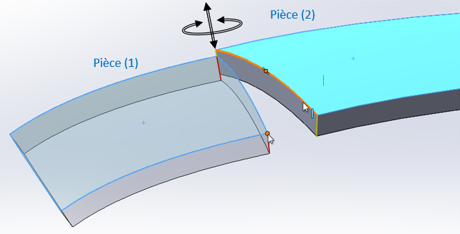
In the absence of the non-existent " coaxiality of the faces ", this procedure makes it possible to make two planes belonging to each part coincide.
First of all, thank you for your detailed answer, I'll make it during the day and I'll keep you informed but I'm having another problem because as I said before, my goal is to create a car shell so that it can then be 3d printable. It will then be necessary for all my pieces to form only one
Do you have any idea about this problem?
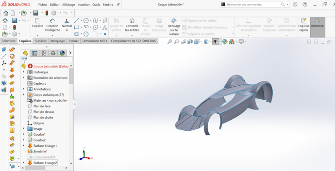
I'm sending you a picture of my car shell in surface which is not totally finished
Hello @mathis.hsf
The easiest way is to save the assembly in parts.
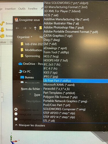
Make " save as " and then without changing the name just change the extension by selecting it from the possible file extension choices.
Once you have your part file, you can back it up again in STL or STEP using the same procedure. it all depends on the format your 3D printer needs.
Kind regards
PS: make sure that the multitude of pieces are all well attached. Otherwise, my colleagues will tell you how to make clean seams because I see that you used surface to generate your shapes.
Otherwise, after 3D printing, you may have holes ![]() . It also depends on the thickness of the bodywork and the method of powder printing, or more likely in your case with wire. Powder printing is more forgiving on thin thicknesses.
. It also depends on the thickness of the bodywork and the method of powder printing, or more likely in your case with wire. Powder printing is more forgiving on thin thicknesses.
PS 2: I suggest you watch this too
Hello @Zozo_mp
You say to change the extension of the file but there are a multitude of them, do you have an idea of which one to choose?
Thank you for your help because I have to finish the hull by May 11th and time is starting to run out
Hello Mathis
Some advice on bodywork to simplify the work:
-
work in L/R symmetry. Model only one side, ensuring that the finished surface is perpendicular to the plane of symmetry.
-
Instead of creating small surfaces that you then glue, prefer a continuity of the surfaces that intersect. Then adjust the surfaces by removing the excess areas. For example, for the top and the bonnet, I would have made a single surface. Then I would have cut the windshield. The front wing another surface and the rear wing a third. Maximum 3-4 surfaces that intersect. Then cut off the excess and the openings.
-
Don't give thickness only at the end. After symmetry. In order for the thickness not to fail, the bending radii must be greater than the thickness.
-
To answer the first question, the same reasoning. Remain on the surface until the end. Connecting two surfaces couldn't be easier. Extend them to make them intertwine, cut off the excess of one in relation to the other. Then sew the two surfaces. Radiate the junction if necessary. Pay attention to the radius, must be greater than the thickness. Then thicken.
So contrary to the advice you received, I would stay in part mode, not assembly. The thickness at the end, not at the beginning.
@soring Thank you very much for your detailed answer
Does this mean that I start my case from 0?
Would it be possible to exchange privately to enlighten me on some points that I don't control and that I finish this hull as soon as possible?
Yes, of course. Sorry for the late reply.
